24: ANALOG I/O CONTROL
« FC4A MICROSMART USER’S MANUAL » 24-9
Ladder Refresh Type Analog I/O Modules
When using a ladder refresh type analog input or output module, the first data register number can be designated in the
ASNT macro dialog box. The quantity of required data registers depends on the model of the ladder refresh type analog
input or output module.
Data register numbers and parameters are shown in the table below.
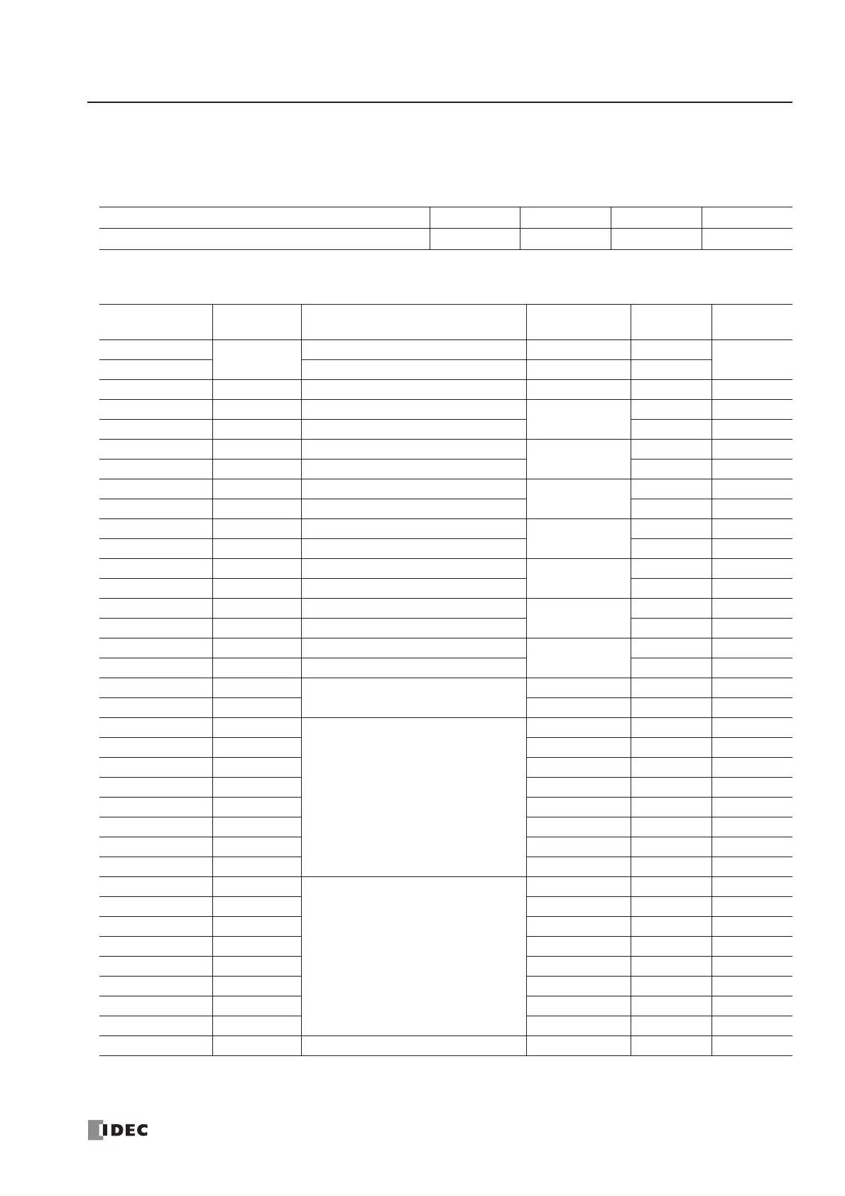
Ladder Refresh Type Analog Input Module Data Register Allocation (FC4A-J4CN1, FC4A-J8C1, and FC4A-J8AT1)
* Data registers for channels 4 through 7 are reser ved on the FC4A-J4CN1.
Analog I/O Module FC4A-J4CN1 FC4A-J8C1 FC4A-J8AT1 FC4A-K2C1
Quantity of Data Registers for Analog I/O Operation 65 65 65 15
Data Register
Number Offset
Data Size
(word)
Parameter Channel Default R/W
+0 (Low Byte)
1
Analog input signal type CH0 FFh
R/W
+0 (High Byte) — Reserved — All channels 00h
+1 4 Analog input data configuration CH0 0 R/W
+5 1 Analog input signal type
CH1
00FFh R/W
+6 4 Analog input data configuration 0 R/W
+10 1 Analog input signal type
CH2
00FFh R/W
+11 4 Analog input data configuration 0 R/W
+15 1 Analog input signal type
CH3
00FFh R/W
+16 4 Analog input data configuration 0 R/W
+20 1 Analog input signal type
CH4 *
00FFh R/W
+21 4 Analog input data configuration 0 R/W
+25 1 Analog input signal type
CH5 *
00FFh R/W
+26 4 Analog input data configuration 0 R/W
+30 1 Analog input signal type
CH6 *
00FFh R/W
+31 4 Analog input data configuration 0 R/W
+35 1 Analog input signal type
CH7 *
00FFh R/W
+36 4 Analog input data configuration 0 R/W
+40 3
Thermistor parameters
(FC4A-J8AT1 only)
CH0 to CH3 0 R/W
+43 3 CH4 to CH7 * 0 R/W
+46 1
Analog input data
CH0 — R
+47 1 CH1 — R
+48 1 CH2 — R
+49 1 CH3 — R
+50 1 CH4 * — R
+51 1 CH5 * — R
+52 1 CH6 * — R
+53 1 CH7 * — R
+54 1
Analog input operating status
CH0 — R
+55 1 CH1 — R
+56 1 CH2 — R
+57 1 CH3 — R
+58 1 CH4 * — R
+59 1 CH5 * — R
+60 1 CH6 * — R
+61 1 CH7 * — R
+62 3 — Reserved — All channels — R