3: INSTALLATION AND WIRING
3-14 « FC4A MICROSMART USER’S MANUAL »
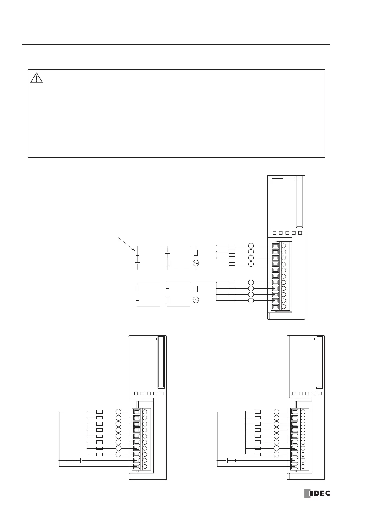
Output Wiring
Relay Output
Transistor Sink Output Transistor Source Output
Caution
• If output relays or transistors in the MicroSmart CPU or output modules should fail, outputs may
remain on or off. For output signals which may cause heavy accidents, provide a monitor circuit
outside the MicroSmart.
• Connect a fuse to the output module, selecting a fuse appropriate for the load.
• Use proper wires for output wiring.
All-in-one type CPU modules: UL1015 AWG22 or UL1007 AWG18
Slim type CPU and I/O modules: UL1015 AWG22
• When equipment containing the MicroSmart is intended for use in European countries, insert an
IEC 60127-approved fuse to each output of every module for protection against overload or
short-circuit. This is required when equipment containing the MicroSmart is destined for Europe.
7 COM1
0
1
2
3
4
5
6
7
Ry.OUT
1023
COM0
NC 456
L
L
Fuse
L
L
L
AC
Fuse
Fuse
DC
DC
Load
L
L
L
Fuse
+
–
AC
Fuse
Fuse
DC
DC
+
–
+
–
+
–
Connect a fuse appropriate
for the load.
Fuse
Fuse
COM(–)
+V
0
1
2
3
4
5
6
7
Tr.OUT
01234567
Connect a fuse
appropriate for the load.
L
Fuse
L
L
+–
L
L
L
L
Load
L
COM(+)
–V
0
1
2
3
4
5
6
7
Tr.OUT
01234567
Connect a fuse
appropriate for the load.
L
Fuse
L
L
+–
L
L
L
L
Load
L
Fuse