28: AS-INTERFACE MASTER COMMUNICATION
28-14 « FC4A MICROSMART USER’S MANUAL »
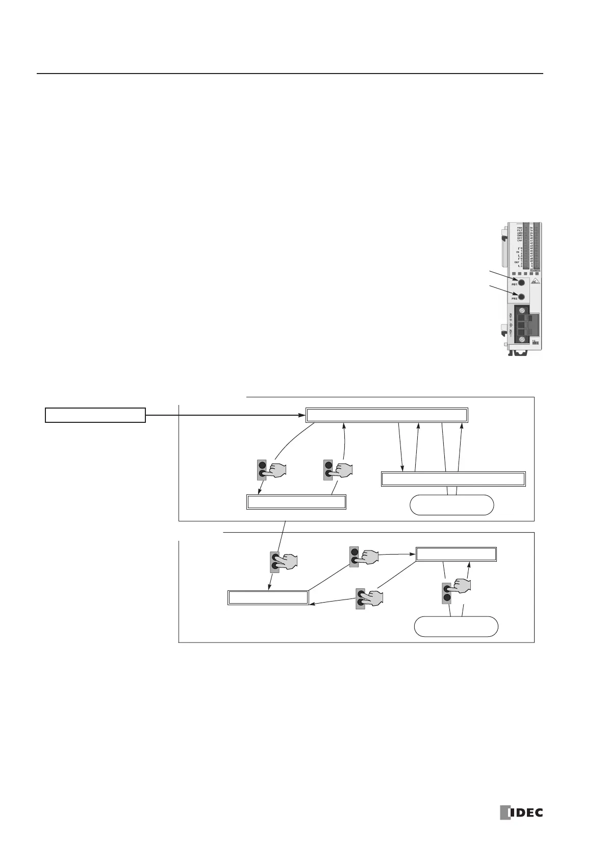
Pushbuttons and LED Indicators
This section describes the operation of pushbuttons PB1 and PB2 on the AS-Interface master module to change operation
modes, and also explains the functions of address and I/O LED indicators.
Pushbutton Operation
The operations performed by pushbuttons PB1 and PB2 on the front of the AS-Interface master module depend on the
duration of being pressed. A “long press” switches the operation mode, and a “short press” switches the slave being moni-
tored on the I/O LEDs. If the duration of pressing PB1 or PB2 does not correspond to either of these, the status of the AS-
Interface master module does not change.
Long Press
A “long press” takes effect when you press either pushbutton PB1 or PB2 or both for 3 seconds or
more. Use the long press to change the operation mode of the AS-Interface master module or to
save the configuration data to the AS-Interface master module EEPROM.
Short Press
A “short press” takes effect when you press either pushbutton PB1 or PB2 for 0.5 second or less.
Use the short press to change the slave address when monitoring slave I/O status on the AS-Inter-
face master module LED indicators.
Transition of AS-Interface Master Module Modes Using Pushbuttons
*1 Pushbutton operation or execution of the ASI command Go to Normal Protected Offline.
*2 Pushbutton operation or execution of the ASI command Go to Normal Protected Mode.
*3 Execution of the ASI command Prohibit Data Exchange.
*4 Execution of the ASI command Enable Data Exchange.
*5 Configuration is done by clicking the Auto Configuration or Manual Configuration button in WindLDR. The configuration
data is saved to the AS-Interface master module EEPROM.