28: AS-INTERFACE MASTER COMMUNICATION
28-16 « FC4A MICROSMART USER’S MANUAL »
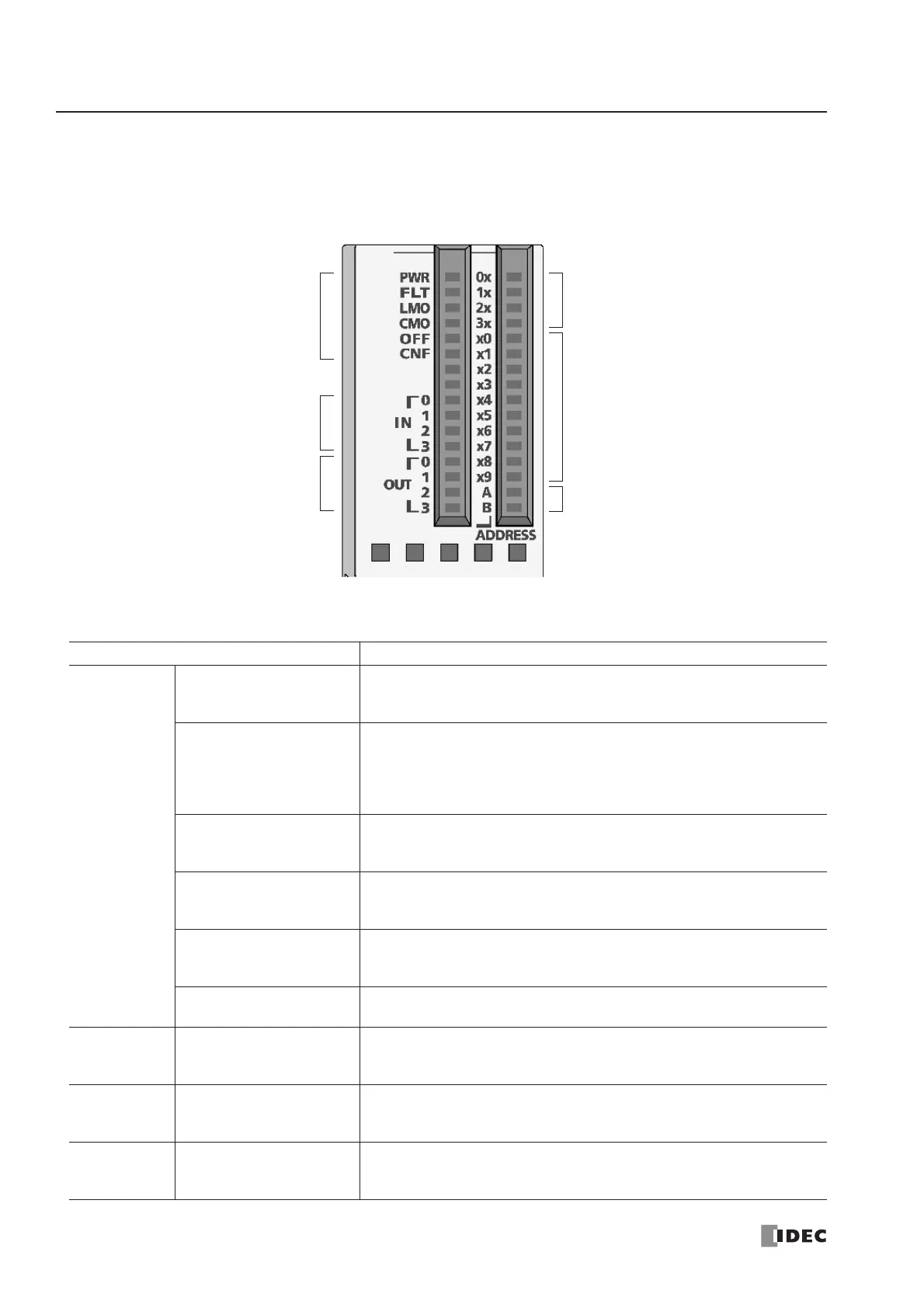
LED Indicators
The LED indicators on the AS-Interface master module consist of status LEDs, I/O LEDs, and address LEDs.
LED Indicators Description
Status LEDs
PWR
(AS-Interface power supply)
Indicates the status of the AS-Interface power supply for the AS-Inter face
master module.
Goes on when the AS-Interface power is supplied sufficiently.
FLT (Fault)
Indicates the AS-Interface configuration status.
Goes on when the permanent configuration data (PCD) stored in the AS-
Interface master module EEPROM does not match the current slave con-
figuration, or configuration data image (CDI). Then, configuration is not
complete or an error was found on the AS-Interface bus.
LMO (Local mode)
Indicates the mode of the AS-Interface master module.
Goes on when the AS-Interface master module is in local mode.
Goes off when the AS-Interface master module is in connected mode.
CMO (Connected mode)
Indicates the mode of the AS-Interface master module.
Goes on when the AS-Interface master module is in connected mode.
Goes off when the AS-Interface master module is in local mode.
OFF (Offline)
Indicates the operating status of the AS-Interface master module.
Goes on when the AS-Interface master module is in normal protected
offline.
CNF (Configuration)
Indicates the configuration status of the AS-Interface master module.
Flashes when the AS-Interface master module is in configuration mode.
Input LEDs IN0-IN3
Indicates the operating status of four inputs at the address indicated by
the address LEDs.
Goes on when the corresponding input at the indicated address is on.
Output LEDs OUT0-OUT3
Indicates the operating status of four outputs at the address indicated by
the address LEDs.
Goes on when the corresponding output at the indicated address is on.
Address LEDs
0x-3x (place of 10)
x0-x9 (place of 1)
A, B (A or B slave)
Indicates the slave address of 0A through 31B.
Goes on when the selected address exists.
Flashes when the selected address does not exist.