28: AS-INTERFACE MASTER COMMUNICATION
« FC4A MICROSMART USER’S MANUAL » 28-17
Status LEDs
The operation modes of the AS-Interface master module can be changed by pressing the pushbuttons on the front of the
AS-Interface master module or by executing ASI commands. The operation modes can be confirmed on the six status
LEDs on the AS-Interface master module. For details about the ASI commands, see page 28-28.
Status LED Indication
*1: Goes off when AS-Interface power is not supplied.
*2: Goes on when an error is found on the AS-Interface bus.
Address LEDs and I/O LEDs
The operating status and I/O status of each slave can be monitored on the address LEDs and I/O LEDs on the front of the
AS-Interface master module.
Slave Operating Status
The operating status of each slave can be determined by viewing the address LEDs and I/O LEDs.
Slave I/O Status
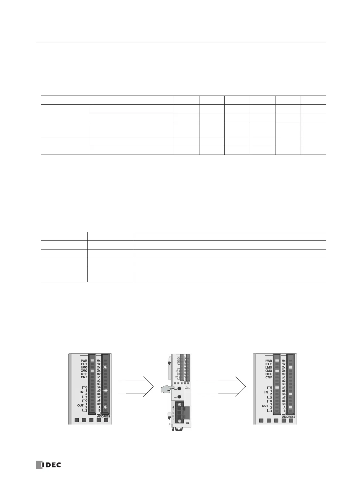
The I/O status of each slave can be monitored on the address LEDs and I/O LEDs. Use the short press to change the slave
address when monitoring slave I/O status on the AS-Interface master module. A short press on PB1 increments the
address. At the last address (31B), another short press will return to the first address (0A). A short press on PB2 decre-
ments the address. At the first address (0A), another short press will return to the last address (31B).
The figures below illustrate what happens when you press the PB1 button while the address LEDs indicate 25A. The
address LEDs increment to 26A where a slave is assigned. Note that the address LEDs flash if no slave is assigned.
Status LED PWR FLT LMO CMO OFF CNF
Connected Mode
Normal Protected Mode ON
*1
OFF
*2
OFF ON OFF OFF
Normal Protected Offline ON
*1
ON OFF ON ON OFF
Normal Protected
Data Exchange Off
ON
*1
ON OFF ON OFF OFF
Local Mode
Protected Mode ON
*1
OFF
*2
ON OFF OFF OFF
Configuration Mode ON
*1
OFF
*2
ON OFF OFF Flash
Address LED I/O LED Description
ON ON or OFF The slave at this address is active.
ON Flash The slave at this address is active, but has an error.
Flash OFF This address is not assigned a slave.
OFF OFF
The AS-Interface bus communication is disabled because the AS-Inter face power
is not supplied or the AS-Interface master module is in normal protected offline.
no slave is assigned.
LEDs indicate the statuses.