2: MODULE SPECIFICATIONS
2-28 « FC4A MICROSMART USER’S MANUAL »
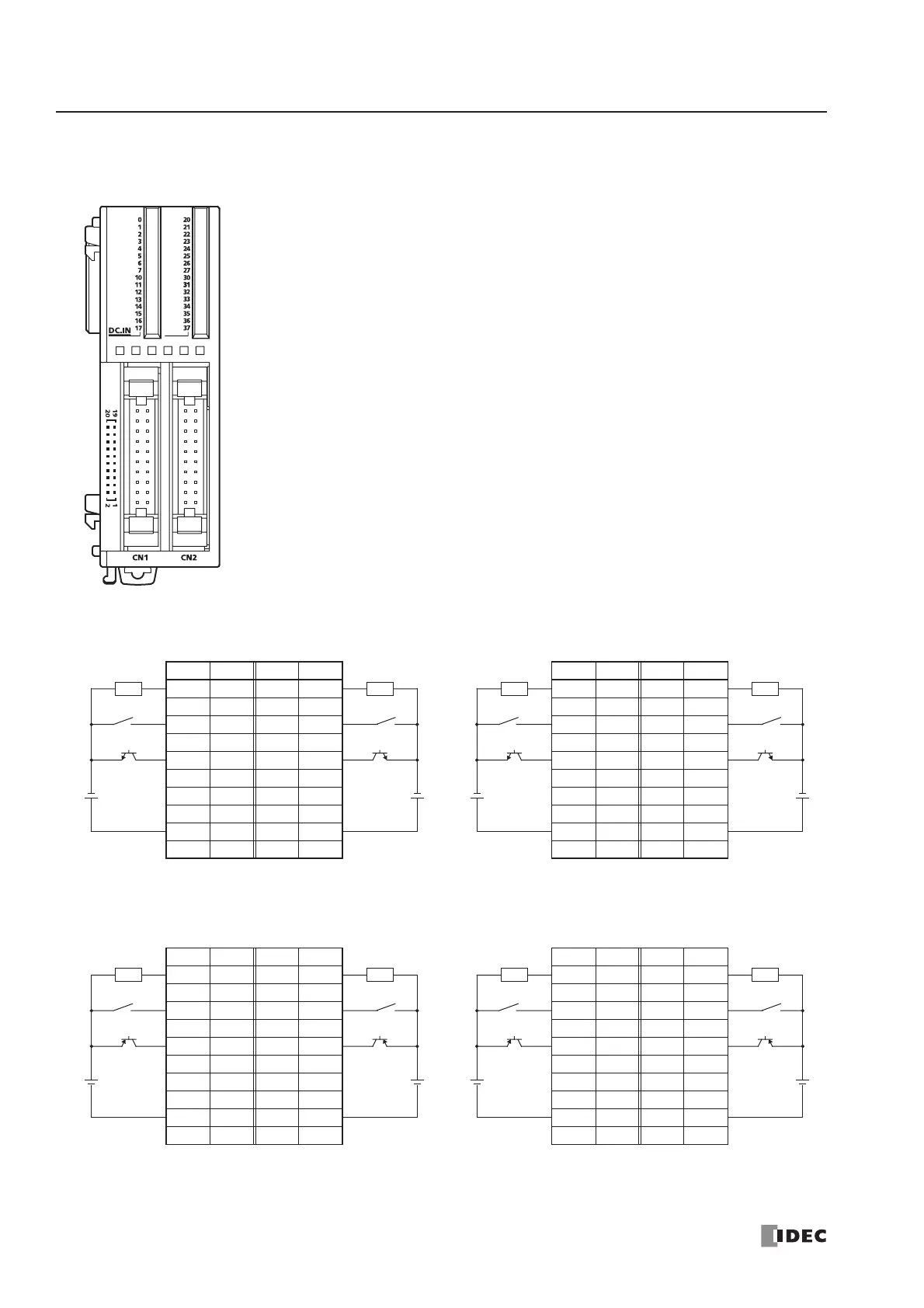
FC4A-N32B3 (32-point DC Input Module) — Connector Type
Applicable Connector: FC4A-PMC20P (not supplied with the input module)
CN1
No. Input No. Input
20 I0 19 I10
18 I1 17 I11
16 I2 15 I12
14 I3 13 I13
12 I4 11 I14
10 I5 9 I15
8I67I16
6I75I17
4 COM0 3 COM0
2NC1NC
Source Input Wiring
• COM0 terminals are connected together internally.
• COM1 terminals are connected together internally.
• COM0 and COM1 terminals are not connected together internally.
• For input wiring precautions, see page 3-13.
+
–
+
–
2-wire Sensor
24V DC
NPN
+
–
+
–
2-wire Sensor
24V DC
NPN
CN2
No. Input No. Input
20 I20 19 I30
18 I21 17 I31
16 I22 15 I32
14 I23 13 I33
12 I24 11 I34
10 I25 9 I35
8 I26 7 I36
6 I27 5 I37
4 COM1 3 COM1
2NC1NC
+
–
+
–
2-wire Sensor
24V DC
NPN
+
–
+
–
2-wire Sensor
24V DC
NPN
CN1
No. Input No. Input
20 I0 19 I10
18 I1 17 I11
16 I2 15 I12
14 I3 13 I13
12 I4 11 I14
10 I5 9 I15
8I67I16
6I75I17
4 COM0 3 COM0
2NC1NC
Sink Input Wiring
+
–
+
–
2-wire Sensor
24V DC
PNP
+
–
+
–
2-wire Sensor
24V DC
PNP
CN2
No. Input No. Input
20 I20 19 I30
18 I21 17 I31
16 I22 15 I32
14 I23 13 I33
12 I24 11 I34
10 I25 9 I35
8 I26 7 I36
6 I27 5 I37
4 COM1 3 COM1
2NC1NC
+
–
+
–
2-wire Sensor
24V DC
PNP
+
–
+
–
2-wire Sensor
24V DC
PNP