2: MODULE SPECIFICATIONS
2-62 « FC4A MICROSMART USER’S MANUAL »
Communication Adapter and Communication Module Specifications
Note 1: RS485 user communication is available on upgraded CPU modules only, see page 17-1.
Note 2: Recommended cable for RS485: Twisted-pair shielded cable with a minimum core wire of 0.3 mm
2
.
Conductor resistance 85 Ω/km maximum, shield resistance 20 Ω/km maximum.
The proper tightening torque of the terminal screws on the RS485 communication adapter and RS485 communication mod-
ule is 0.22 to 0.25 N·m. For tightening the screws, use screwdriver SZS 0,4 x 2,5 (Phoenix Contact).
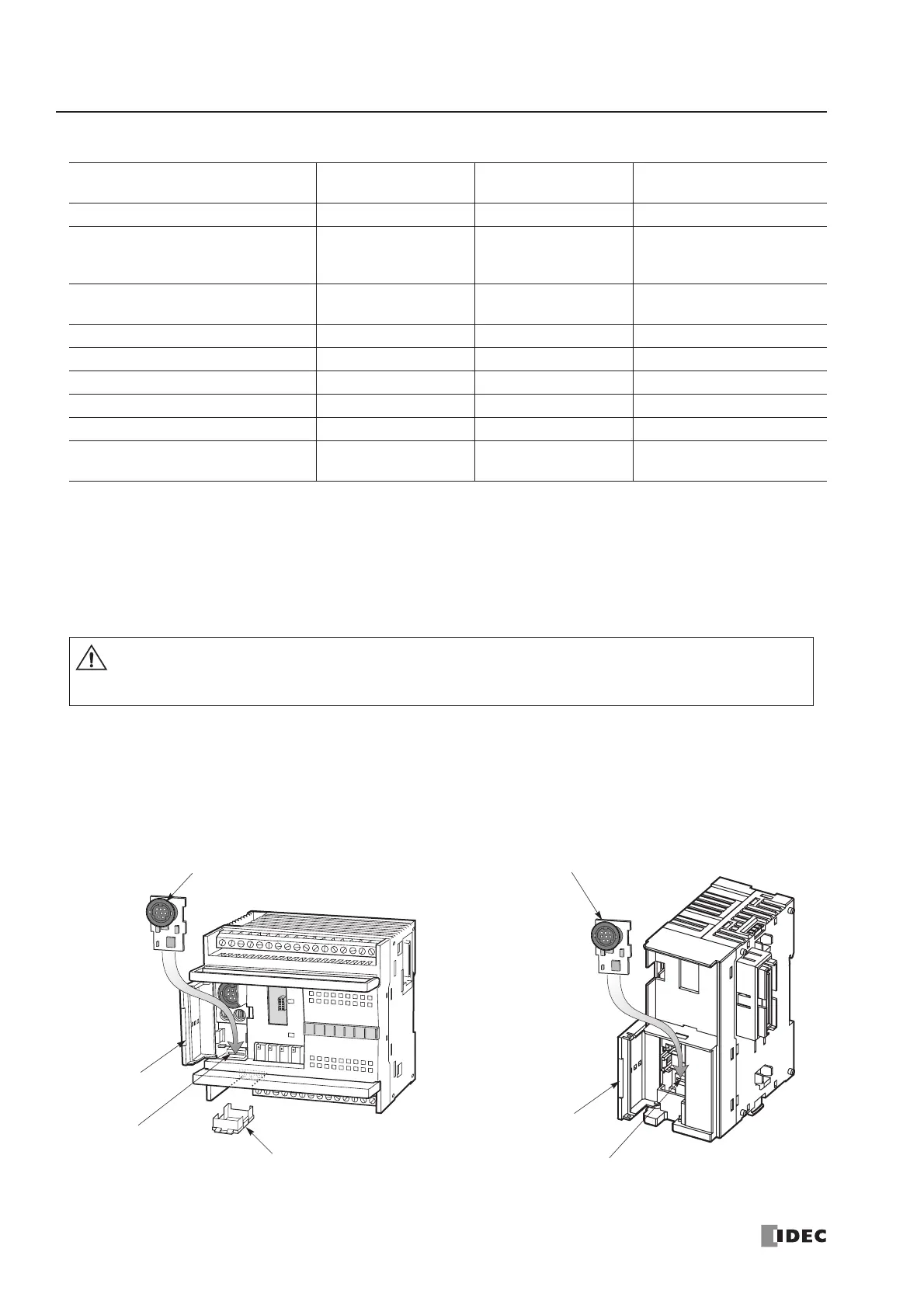
Installing the Communication Adapter and Communication Module
Communication Adapter
To install the communication adapter on the all-in-one type CPU module, open the hinged lid and remove the dummy car-
tridge. Push the communication adapter into the port 2 connector from the front until it bottoms and is secured by the
latches. Similarly, when installing the communication adapter on the HMI base module, open the hinged lid, and push the
communication adapter into the port 2 connector from the front until it bottoms and is secured by the latches.
Type No.
FC4A-PC1
FC4A-HPC1
FC4A-PC2
FC4A-HPC2
FC4A-PC3
FC4A-HPC3
Standards EIA RS232C EIA RS485 EIA RS485
Maximum Baud Rate 19,200 bps 19,200 bps
Computer link: 19,200 bps
User com.: 19,200 bps
Data link: 38,400 bps
Maintenance Communication
(Computer Link)
Possible Possible Possible
User Communication Possible Not possible Possible (Note 1)
Modem Communication Possible Not possible Not possible
Data Link Communication Not possible Not possible Possible
Quantity of Slave Stations ——31
Maximum Cable Length Special cable Special cable 200m (Note 2)
Isolation between Internal Circuit
and Communication Port
Not isolated Not isolated Not isolated
CPU module. Otherwise, the communication adapter or CPU module may be dam-