2: MODULE SPECIFICATIONS
« FC4A MICROSMART USER’S MANUAL » 2-63
After installing the communication adapter on an all-in-one
type CPU module, view the communication adapter through
the dummy cartridge opening, and check to see that the PC
board of the communication adapter is in a lower level than the
top of the terminal block.
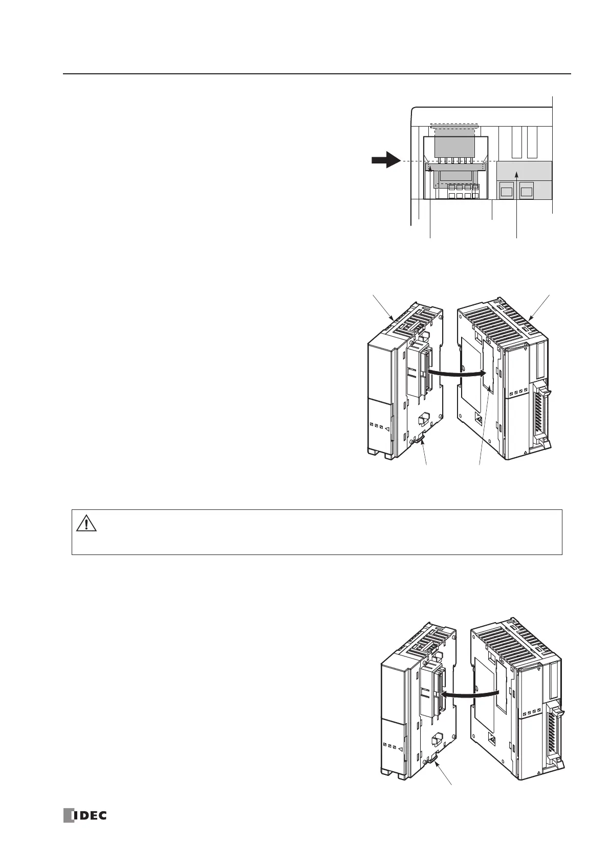
Communication Module
When installing a communication module on the slim type
CPU module, remove the communication connector cover
from the slim type CPU module. See page 3-6.
Place the communication module and CPU module side by
side. Put the communication connectors together for easy
alignment.
With the communication connectors aligned correctly and the
blue unlatch button in the down position, press the communica-
tion module and CPU module together until the latches click to
attach the modules together firmly. If the unlatch button is in
the up position, push down the button to engage the latches.
Removing the Communication Adapter and Communication Module
Communication Adapter
To remove the communication adapter from the all-in-one type
CPU module, first remove the dummy cartridge. While pushing
up the communication adapter PC board with a finger through
the dummy cartridge opening, disengage the latches from the
communication adapter using a flat screwdriver. Pull out the
communication adapter from the port 2 connector. When
removing the communication adapter from the HMI module,
take similar steps.
Communication Module
If the modules are mounted on a DIN rail, first remove the
modules from the DIN rail as described on page 3-7.
Push up the blue unlatch button to disengage the latches, and
pull the modules apart as shown on the right.