15
HS5L Interlock Switch with Solenoid (4-Contact)
0
Approx. 26.4
Approx. 5.3
Approx. 6.9
Approx. 3.3 (Locked position)
(Stroke: mm)
(Actuator insertion position)
: Contacts OFF
(open)
: Contacts ON
(closed)
Main Circuit
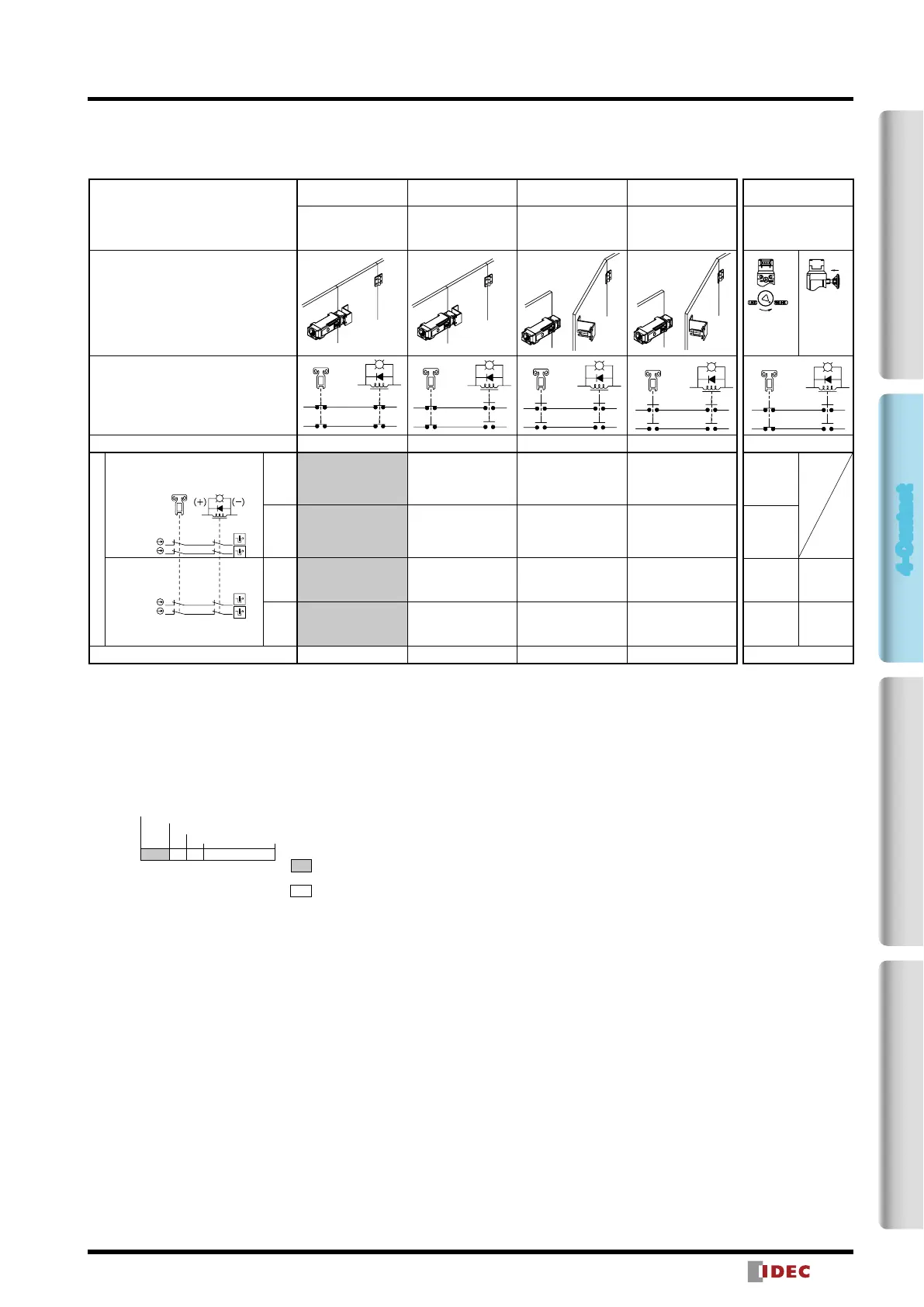
Circuit Diagrams and Operating Characteristics
4-Contact / Dual Safety Circuit, 4-Contact / Dual Safety Circuit / Rear Unlocking Button (Spring Lock)
Interlock Switch Status
Status 1 Status 2 Status 3 Status 4
Door Closed
Machine ready to
operate
Solenoid de-energized
Door Closed
Machine cannot be
operated
Solenoid energized
Door open
Machine cannot be
operated
Solenoid energized
Door open
Machine cannot be
operated
Solenoid de-energized
Door Status
Circuit Example: HS5L-DD4
(−
(+)
A2
A1
5221
11 42
5122
12 41
(−
(+)
A2
A1
52512221
11 12 4241
(−
(+)
A2
A1
5221
11 42
5122
12 41
(−
(+)
A2
A1
5221
11 42
5122
12 41
Door
Closed (locked) Closed (unlocked) Open Open
Part No. and Circuit Diagram
HS5L-DD44
A1A2
Main Circuit:
11 12 4241
21
Main Circuit:
525122
Main Circuit:
11 12 4241
21
Main Circuit:
525122
Door Monitor
(Actuator inserted)
Lock Monitor
(Solenoid OFF)
Main
Circuit
11−42
Main
Circuit
21−52
HS5L-DD44L
Main
Circuit
11−42
Main
Circuit
21−52
Solenoid Power A1-A2 (all model)
OFF (de-energized) ON (energized) ON (energized) OFF (de-energized)
Note 1: Actuator can be unlocked manually for conrming the door movement before wiring and energizing, and also for emergency
situation such as power failure.
Note 2: When the operator is conned in a hazardous zone, the actuator can be unlocked manually by pressing the rear unlocking button.
(Only for the type with rear unlocking button)
• The contact conguration shows the status when the actuator is inserted and the switch is locked.
• Main Circuit: Connected to the control circuit of machine drive part, sending interlock signals of the protective door.
• For safety circuit input, connect to the monitor circuit.
Operating Characteristics (Reference)
Unlocking using
Manual Unlock Key
Door Closed
Machine cannot be
operated
Solenoid de-energized
Press
·Turn the
manual
unlock key
(Note 1)
·Press the
rear
unlocking
button
(Note 2)
(−
(+)
A2
A1
5221
11 42
5122
12 41
Closed (unlocked)
OFF (de-energized)
• The operation characteristics shown in the chart above are of the HS9Z-A51. For other actuators, add 1.3mm.
• See page 21 for HS9Z-BA5.
• The operation characteristics show the contact status when the actuator enters the entry slot of an interlock switch.
2-Contact4-ContactActuatorDimensions / Instructions
 Loading...