8
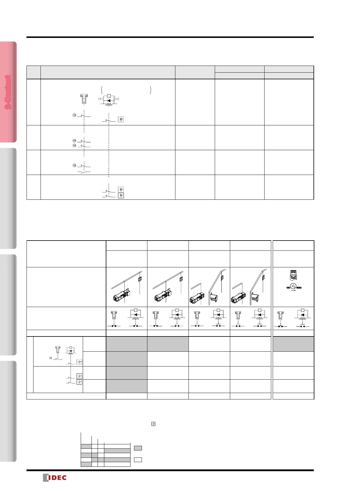
HS5L Interlock Switches with Solenoid (2-Contact)
2-Contact Package Quantity: 1
Circuit
Code
Contact Conguration Gland Port Size
Spring lock Solenoid
Part No. Part No.
XD
M20
HS5L-XD44M-G HS5L-XD7Y4M-G
XF M20 — HS5L-XF7Y4M-G
XG M20 — HS5L-XG7Y4M-G
XH
M20
HS5L-XH44M-G HS5L-XH7Y4M-G
Note: This marking cannot be applied to solenoid locks according to general requirement (5.7.1) in ISO14119.
• The contact conguration shows the status when the actuator is inserted and the switch is locked.
• Actuators are not supplied with the interlock switch and must be ordered separately.
Monitor Circuit:
2423
1211
1211
Monitor Circuit:
Monitor Circuit:
Monitor Circuit:
4241
A2 A1
4241
5251
Monitor Circuit:
Monitor Circuit:
21 22
1211
Monitor Circuit:
Monitor Circuit:
Door Monitor
(Actuator inserted)
Lock Monitor
Spring lock→Solenoid OFF
Solenoid lock→Solenoid ON
(Note)
(Note)
(Note)
Circuit Diagrams and Operating Characteristics
Spring Lock
Interlock Switch Status
Status 1 Status 2 Status 3 Status 4
Door Closed
Machine ready to
operate
Solenoid de-energized
Door Closed
Machine cannot be
operated
Solenoid energized
Door open
Machine cannot be
operated
Solenoid energized
Door open
Machine cannot be
operated
Solenoid de-energized
Door Status
Circuit Example: HS5L-XD4
11 12 4241
(−
(+)
A2
A1
A2
A1
11 12 4241
A2
A1
424111 12
A2
A1
424111 12
Door Closed (locked) Closed (unlocked) Open Open
Part No. Circuit Diagram
4241
5251
1211
(−)(+)
A2 A1
Monitor Circuit:
Monitor Circuit:
Monitor Circuit:
Monitor Circuit:
4241
(Actuator inserted)
(Solenoid OFF)
HS5L-XD4
Monitor Circuit
(door closed)
11-12
Monitor Circuit
(locked)
41-42
HS5L-XH4
Monitor Circuit
(locked)
41-42
Monitor Circuit
(locked)
51-52
Solenoid Power A1-A2 (common to all types) OFF (de-energized) ON (energized) ON (energized) OFF (de-energized)
• The contact conguration shows the status when the actuator is inserted and the
switch is locked.
• Monitor Circuit: Sends monitoring signals of protective door open/closed status
(door monitor) or protective door lock/unlock status (lock monitor).
• For safety circuit input, connect to the monitor circuit with marking.
When unlocking
manually
Door Closed
Machine cannot be
operated
Solenoid de-energized
Turn the manual
unlock key
(Note)
(−
(+)
A2
A1
11 12 4241
Closed (unlocked)
OFF (de-energized)
HS5L Interlock Switches with Solenoid (2-Contact)
Approx. 26.4
Approx. 5.3
Approx. 6.9
Approx. 3.3 (Locked position)
(Stroke: mm)
(Actuator Mounting Reference Position)
: Contacts OFF
(open)
: Contacts ON
(closed)
Lock Monitor Circuit (unlocked, NO)
Main Circuit
Door Monitor Circuit (door open, NO)
Lock Monitor Circuit (locked, NC)
Door Monitor Circuit (door closed, NC)
Note: Actuator can be unlocked manually for
conrming the door movement before wiring
and energizing, and also for emergency
situation such as power failure.
• The operation characteristics shown in the chart are for HS9Z-A51.
For other actuators, add 1.3mm.
• See page 21 for HS9Z-BA5.
• The operation characteristics show the contact status when the
actuator enters the entry port of an interlock switch.
2-Contact4-ContactActuatorDimensions / Instructions
Lock Monitor Circuit: 1NC
Lock Monitor Circuit: 2NC
Door Monitor Circuit: 1NC
Door Monitor Circuit: 2NC
Door Monitor Circuit: 1NC,1NO
 Loading...