9
Monitor Circuit:
Monitor Circuit:
Monitor Circuit:
Monitor Circuit:
Monitor Circuit:
Monitor Circuit:
Monitor Circuit:
Monitor Circuit:
4241
5251
2423
1211
21 22
1211
4241
1211
A2 A1
Door Monitor
(Actuator
inserted)
Lock Monitor
(Solenoid ON)
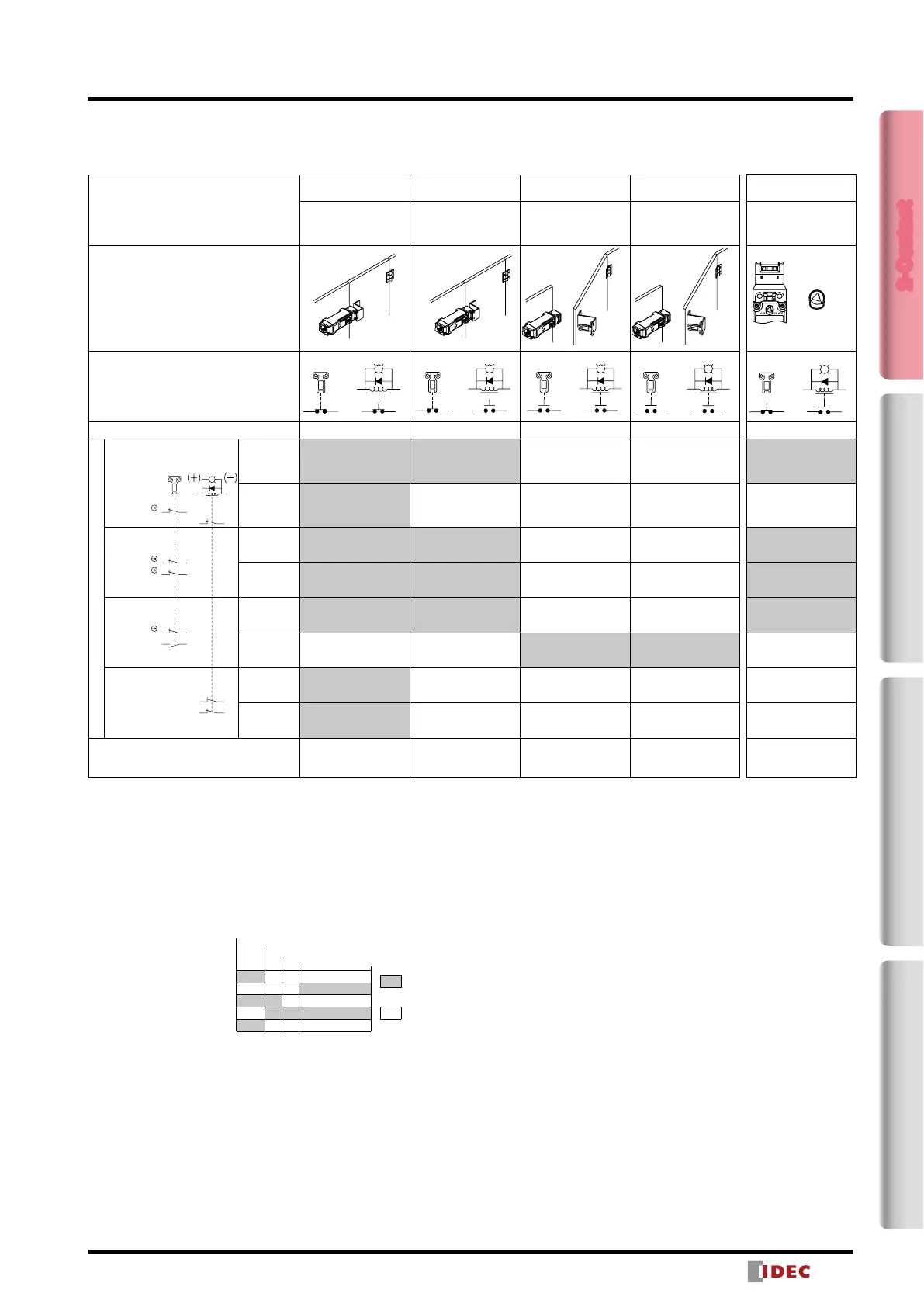
HS5L Interlock Switches with Solenoid (2-Contact)
Circuit Diagrams and Operating Characteristics
Solenoid Lock
Interlock Switch Status
Status 1 Status 2 Status 3 Status 4
Door Closed
Machine ready to
operate
Solenoid energized
Door Closed
Machine cannot be
operated
Solenoid de-energized
Door open
Machine cannot be
operated
Solenoid de-energized
Door open
Machine cannot be
operated
Solenoid energized
Door Status
Circuit Example: HS5L-XD7Y
Door Closed (locked) Closed (unlocked) Open Open
Part No. and Circuit Diagram
HS5L-XD7Y
Monitor Circuit
(door closed)
11-12
Monitor Circuit
(locked)
41-42
HS5L-XF7Y (Note 3)
Monitor Circuit
(door closed)
11-12
Monitor Circuit
(door closed)
21-22
HS5L-XG7Y (Note 3)
Monitor Circuit
(door closed)
11-12
Monitor Circuit
(door open)
23-24
HS5L-XH7Y
Monitor Circuit
(locked)
41-42
Monitor Circuit
(locked)
51-52
Solenoid Power A1-A2 (all models) OFF (energized) OFF (de-energized) OFF (de-energized)
ON (energized)
(Note 2)
Note 1: Do not unlock manually while the solenoid is energized.
Note 2: Do not energize the solenoid for a long period of time while the door is open or while the door is unlocked
manually.
Note 3: Circuit codes XF and XG do not have signals to notify whether the switch is locked or unlocked. A different
method should be used to check the lock status.
• The contact conguration shows the status when the actuator is inserted and the switch is locked.
• Monitor Circuit: Sends monitoring signals of protective door open/closed status (door monitor) or protective door
lock/unlock status (lock monitor).
Operation Characteristics (Reference)
Unlocking using
Manual Unlock Key
Door Closed
Machine cannot be operated
Solenoid de-energized
➝
energized
When unlocking
manually
UNLOCKLOCK
Closed (unlocked)
(Note 1) (Note 2)
OFF (de-energized)
➝
ON (energized)
Approx. 26.4
Approx. 5.3
Approx. 6.9
Approx. 3.3 (Locked position)
0
(Stroke: mm)
(Actuator Mounting Reference Position)
: Contacts OFF
(open)
: Contacts ON
(closed)
Lock Monitor Circuit (unlocked, NO)
Main Circuit
Door Monitor Circuit (door open, NO)
Lock Monitor Circuit (locked, NC)
Door Monitor Circuit (door closed, NC)
11 12 4241
(−
(+)
A2
A1
(−
(+)
A2
A1
11 12 4241
(−
(+)
A2
A1
424111 12
(−
(+)
A2
A1
424111 12
(−
(+)
A2
A1
11 12 4241
• The operation characteristics shown in the chart above are for HS9Z-A51. For other actuators, add 1.3mm.
• See page 21 for HS9Z-BA5.
• The operation characteristics show the contact status when the actuator enters the entry port of an interlock switch.
2-Contact4-ContactActuatorDimensions / Instructions
 Loading...