2: P
RODUCT
S
PECIFICATIONS
2-48 FC6A S
ERIES
MICROS
MART
U
SER
’
S
M
ANUAL
FC9Y-B1722
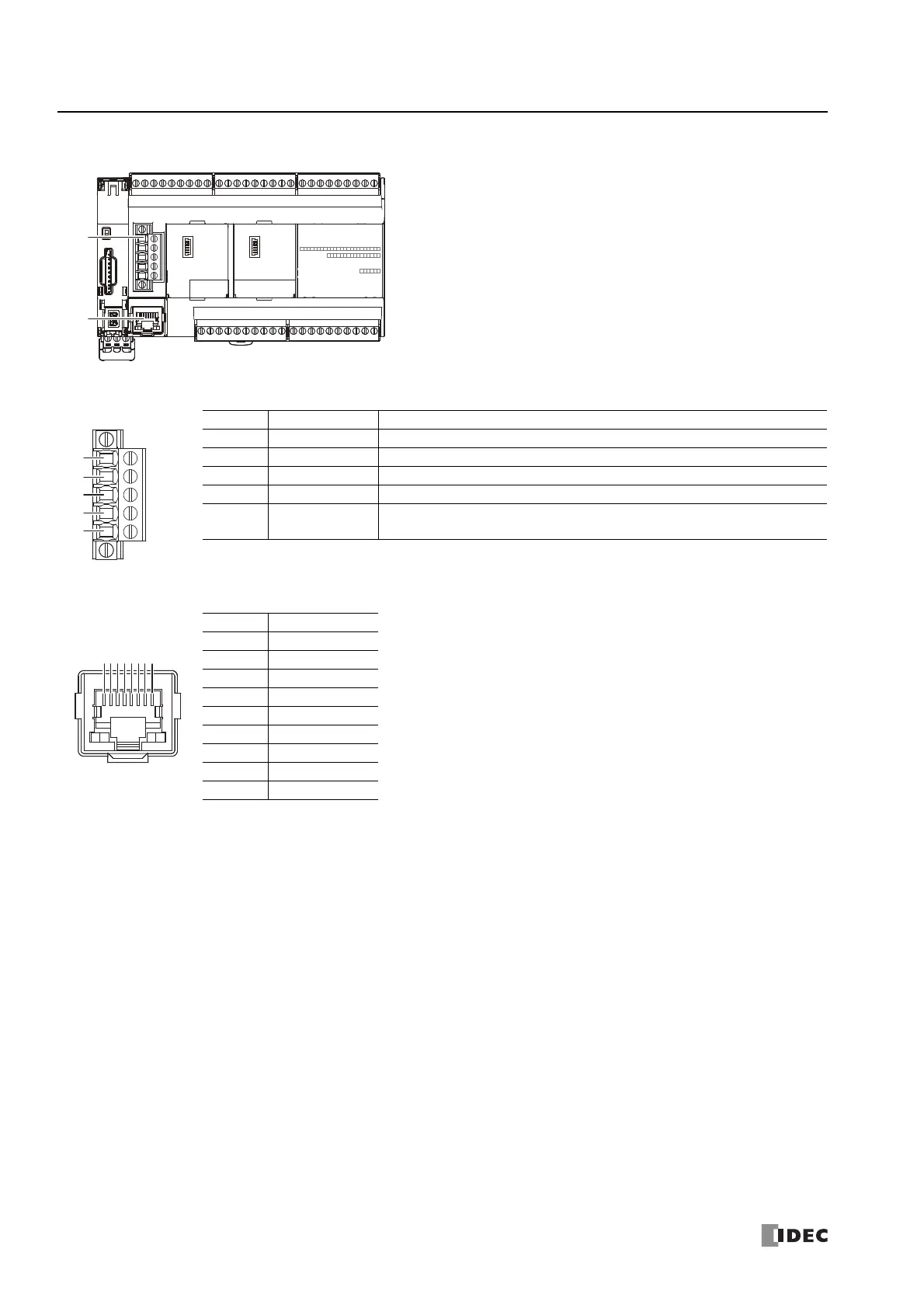
■ CAN J1939 All-in-One CPU module
(1) CAN port
(2) Ethernet Port 1
No. Signal Wire Description
1 SG CAN external power supply (-)
2 CAN_L CAN_L bus line (dominant low)
3 CAN_SHLD CAN cable shield
*1
4 CAN_H CAN_H bus line (dominant high)
5(V+)
CAN external power supply (+).
(This port is not used with the FC6A Series MICROSmart.)
*1 Internally connected to the SG via a resistor and capacitor connected in a series. (R = 1 Ω, 0.68 μF)
Applicable connector: FC6A-PMTE05PN02 (screw fastened type), FC6A-PMSE05PN02 (push-in type)
No. Signal Wire
1TPO+
2TPO-
3TPI+
4 ―
5 ―
6TPI-
7 ―
8 ―
Shell
*1
Shield
*1 Shell is connected to PE or FE on the power supply terminals.
87654321
 Loading...
