2021-11-08
17
IDS NXT: Technical manual IDS NXT rome
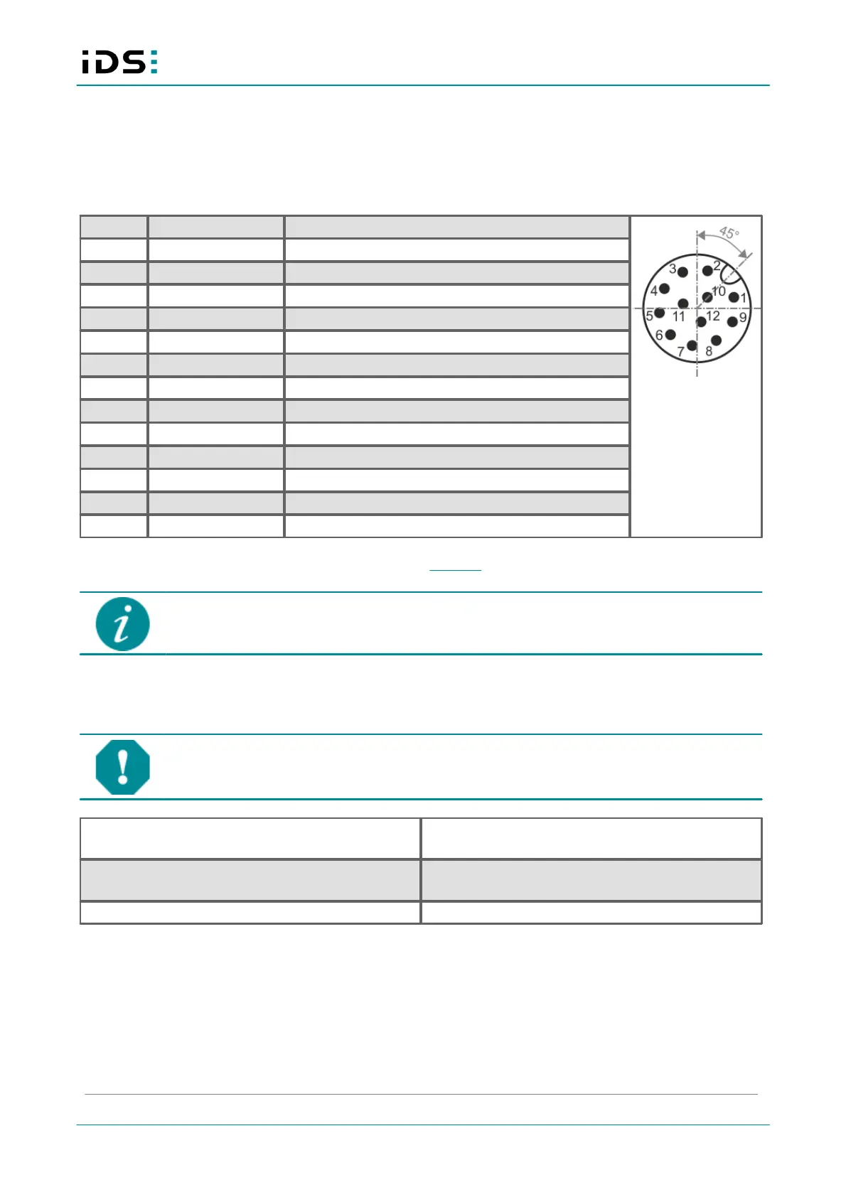
7.2 Pin assignment I/O connector
12-pin M12 connector (Attend 216A-12MSR)
Fig. 4: I/O connector,
camera rear view
Power supply: 12-24 V DC +20 %
Reference level (ground) for power supply and RS-232
Trigger input with optocoupler
Reference level for all Opto IN
Reference level for all Opto OUT
Output 1 with optocoupler
Output 2 with optocoupler
Flash output with optocoupler
You can check the color assignment of the cable on the Website directly at the specific accessory item.
The maximum length of the I/O cable is 30 m. The cable must be shielded.
Power supply
NOTICE! The camera can be supplied with voltage both from an external source and via
Power-over-Ethernet (PoE). The camera should not be supplied through both voltage sources
at once as this can irreparably damage the camera.
Input I/O connector (M12): 12-24 V DC +20 %
Input GigE connector (RJ45): PoE 41-57 V DC
Input I/O connector (M12): min. 1 A
Input GigE connector (RJ45): min. 350 mA
IDS Imaging Development Systems GmbH recommends to adjust the power supply to the power requirement
of the camera to limit overheating in case of short circuit.
To ensure the electrical safety, the camera power supply must meet the requirements for SELV (safety extra
low voltage) / LPS (limited power source) or ES1 / PS2. The camera power supply must be rated by the values
given in the table above. It also must ensure that the voltage values given in the table above are available at the
input of the camera.