Home
IEI Technology
Motherboard
IMBA-C2060
IEI Technology IMBA-C2060 - User Manual
209 pages
Manual
Specs
Ask a question
Save Page as PDF
To Next Page
To Next Page
Loading...
IMBA-C2060 A
TX
Motherboard
Page i
User Manual
MODEL:
IMBA-C2060
A
TX LGA1
155 Motherboard for Inte
l® Core™ i3 Quad/Dual Core
CPU, Intel® C206 Chip
set, DDR3, VGA/DVI/HDMI,
Dual Intel® PCIe GbE, Intel®
AMT 7.0 Support, T
wo USB 3.0
Port
s, Five COM Port
s, T
wo SA
T
A
6Gb/s Port
s and RoHS
Rev
. 2.01 – 23
April, 2014
2
Table of Contents
Main Page
Default Chapter
1
User Manual
1
Table of Contents
4
1 Introduction
17
Introduction
18
Benefits
18
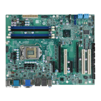
Figure 1-1: IMBA-C2060
18
Features
19
Connectors
20
Figure 1-2: Connectors
20
Dimensions
21
Figure 1-3: IMBA-C2060 Dimensions (MM)
21
Data Flow
22
Figure 1-4: Data Flow Diagram
22
Technical Specifications
23
Table 1-1: IMBA-C2060 Specifications
24
2 Packing List
25
Anti-Static Precautions
26
Unpacking Precautions
26
Packing List
27
Optional Items
28
Table 2-1: Packing List
28
Table 2-2: Optional Items
29
3 Connectors
30
Peripheral Interface Connectors
31
IMBA-C2060 Layout
31
Figure 3-1: Connectors and Jumpers
31
Peripheral Interface Connectors
32
External Interface Panel Connectors
33
Table 3-1: Peripheral Interface Connectors
33
Table 3-2: Rear Panel Connectors
33
Internal Peripheral Connectors
34
ATX Power Connector
34
Figure 3-2: ATX Power Connector Pinout Location
34
Battery Connectors
35
Table 3-3: ATX Power Connector Pinouts
35
CPU Power Connector
36
Figure 3-3: Battery Connector Locations
36
Table 3-4: Battery Connector (BT2) Pinouts
36
DDR3 DIMM Slots
37
Figure 3-4: CPU Power Connector Location
37
Table 3-5: CPU Power Connector Pinouts
37
Digital I/O Connector
38
Figure 3-5: DDR3 DIMM Slot Locations
38
Fan Connector (CPU)
39
Figure 3-6: Digital I/O Connector Location
39
Table 3-6: Digital I/O Connector Pinouts
39
Fan Connector (System)
40
Figure 3-7: CPU Fan Connector Location
40
Table 3-7: CPU Fan Connector Pinouts
40
Front Panel Audio Connector
41
Figure 3-8: System Fan Connector Location
41
Table 3-8: System Fan Connector Pinouts
41
Front Panel Connector
42
Figure 3-9: Front Panel Audio Connector Location
42
Table 3-9: Front Panel Audio Connector Pinouts
42
I2C Connector
43
Figure 3-10: Front Panel Connector Location
43
Table 3-10: Front Panel Connector Pinouts
43
Keyboard/Mouse Connector
44
Figure 3-11: I2C Connector Location
44
Table 3-11: I2C Connector Pinouts
44
Parallel Port Connector
45
Figure 3-12: Keyboard/Mouse Connector Location
45
Table 3-12: Keyboard/Mouse Connector Pinouts
45
PCI Slots
46
Figure 3-13: Parallel Port Connector Location
46
Table 3-13: Parallel Port Connector Pinouts
46
Pcie X4 Slots
47
Figure 3-14: PCI Slot Locations
47
Figure 3-15: Pcie X4 Slot Locations
47
Pcie X8 Slot
48
PCI Express X16/X8 Slot
48
Figure 3-16: Pcie X8 Slot Location
48
SATA 3Gb/S Drive Connector
49
Figure 3-17: Pcie X16 Slot Location
49
SATA 6Gb/S Drive Connector
50
Figure 3-18: SATA 3Gb/S Drive Connector Location
50
Table 3-14: SATA 3Gb/S Drive Connector Pinouts
50
Serial Port Connector, RS-422/485
51
Figure 3-19: SATA 6Gb/S Drive Connector Location
51
Table 3-15: SATA 6Gb/S Drive Connector Pinouts
51
Figure 3-20: RS-422/485 Connector Location
52
Table 3-16: RS-422/485Connector Pinouts
52
Table 3-17: D-Sub 9 RS-422/485 Pinouts
52
Serial Port Connectors, RS-232
53
Smbus Connector
53
Figure 3-21: Serial Port Connector Location
53
Table 3-18: Serial Port Connector Pinouts
53
SPDIF Connector
54
Figure 3-22: Smbus Connector Location
54
Table 3-19: Smbus Connector Pinouts
54
SPI ROM Connector
55
Figure 3-23: SPDIF Connector Location
55
Table 3-20: SPDIF Connector Pinouts
55
TPM Connector
56
Figure 3-24: SPI Connector Location
56
Table 3-21: SPI Connector Pinouts
56
USB Connectors
57
Figure 3-25: TPM Connector Location
57
Table 3-22: TPM Connector Pinouts
57
Figure 3-26: USB Connector Pinout Locations
58
Table 3-23: USB Port Connector Pinouts
58
External Peripheral Interface Connector Panel
59
Audio Connector
59
Figure 3-27: External Peripheral Interface Connector
59
Ethernet and USB Connector
60
Figure 3-28: Audio Connector
60
Figure 3-29: Ethernet Connector
60
Table 3-24: LAN Pinouts
60
HDMI Port Connector
61
Table 3-25: Connector Leds
61
Table 3-26: USB Port Pinouts
61
Keyboard/Mouse Connector
62
Serial Port Connectors (COM6)
62
Table 3-27: HDMI Connector Pinouts
62
Table 3-28: PS/2 Connector Pinouts
62
VGA and DVI Connector
63
Figure 3-30: Serial Port Connector Pinouts
63
Table 3-29: Serial Port Connector Pinouts
63
Table 3-30: VGA Connector Pinouts
63
Figure 3-31: VGA Connector
64
Table 3-31: DVI Connector Pinouts
64
4 Installation
65
Anti-Static Precautions
66
Installation Considerations
66
Socket LGA1155 CPU Installation
68
Figure 4-1: Disengage the CPU Socket Load Lever
68
Figure 4-2: Remove Protective Cover
69
Figure 4-3: Insert the Socket LGA1155 CPU
70
Figure 4-4: Close the Socket LGA1155
70
Socket LGA1155 Cooling Kit Installation
71
Figure 4-5: Cooling Kits (CF-1156A-RS and CF-1156E-RS)
71
Figure 4-6: Cooling Kit Support Bracket
72
DIMM Installation
73
Figure 4-7: DIMM Installation
73
Jumper Settings
74
AT/ATX Power Select Jumper
74
Table 4-1: Jumpers
74
Clear CMOS Jumper
75
Figure 4-8: AT/ATX Power Mode Jumper Location
75
Table 4-2: AT/ATX Power Mode Jumper Settings
75
Table 4-3: Clear BIOS Jumper Settings
75
Wake-On LAN Jumper
76
Figure 4-9: Clear BIOS Jumper Location
76
Table 4-4: Wake-On LAN Connector Pinouts
76
Internal Peripheral Device Connections
77
SATA Drive Connection
77
Figure 4-10: Wake-On LAN Connector Pinout Locations
77
Figure 4-11: SATA Drive Cable Connection
78
Figure 4-12: SATA Power Drive Connection
78
External Peripheral Interface Connection
79
Audio Connector
79
Figure 4-13: Audio Connector
79
DVI Display Device Connection
80
Figure 4-14: DVI Connector
80
HDMI Connection
81
Figure 4-15: HDMI Connection
81
LAN Connection
82
PS/2 Keyboard and Mouse Connection
82
Figure 4-16: LAN Connection
82
Serial Device Connection
83
Figure 4-17: PS/2 Keyboard/Mouse Connector
83
USB Connection (Dual Connector)
84
Figure 4-18: Serial Device Connector
84
VGA Monitor Connection
85
Figure 4-19: USB Connector
85
Intel ® Amt Setup Procedure
86
Figure 4-20: VGA Connector
86
5 Bios
88
Introduction
89
Starting Setup
89
Using Setup
89
Getting Help
90
Unable to Reboot after Configuration Changes
90
BIOS Menu Bar
90
Table 5-1: BIOS Navigation Keys
90
Main
91
BIOS Menu 1: Main
91
Advanced
92
ACPI Settings
93
BIOS Menu 2: Advanced
93
BIOS Menu 3: ACPI Configuration
93
Trusted Computing
94
BIOS Menu 4: TPM Configuration
94
CPU Configuration
95
BIOS Menu 5: CPU Configuration
95
CPU Information
96
BIOS Menu 6: CPU Configuration
96
SATA Configuration
98
BIOS Menu 7: SATA Configuration
98
Intel TXT(LT) Configuration
99
USB Configuration
100
BIOS Menu 8: Intel TXT(LT) Configuration
100
BIOS Menu 9: USB Configuration
100
Super IO Configuration
102
BIOS Menu 10: Super IO Configuration
102
Serial Port N Configuration
103
BIOS Menu 11: Serial Port N Configuration Menu
103
Parallel Port Configuration
109
BIOS Menu 12: Parallel Port Configuration Menu
109
H/W Monitor
110
BIOS Menu 13: H/W Monitor
110
FAN 1 Configuration
111
BIOS Menu 14: FAN 1 Configuration
112
FAN 2 Configuration
113
BIOS Menu 15: FAN 2 Configuration
114
Serial Port Console Redirection
115
BIOS Menu 16: Serial Port Console Redirection
116
Chipset
117
North Bridge Configuration
118
BIOS Menu 17: Chipset
118
BIOS Menu 18:Northbridge Chipset Configuration
118
South Bridge Configuration
120
BIOS Menu 19: Southbridge Chipset Configuration
121
Integrated Graphics
124
BIOS Menu 20: Integrated Graphics
125
ME Subsystem
126
BIOS Menu 21: ME Subsystem
126
Boot
127
BIOS Menu 22: Boot
127
Security
129
BIOS Menu 23: Security
129
Exit
130
BIOS Menu 24:Exit
130
6 Software Drivers
132
Available Software Drivers
133
Software Installation
133
Figure 6-1: Introduction Screen
134
Figure 6-2: Available Drivers
134
Chipset Driver Installation
135
Figure 6-3: Chipset Driver Screen
135
Figure 6-4: Chipset Driver Welcome Screen
136
Figure 6-5: Chipset Driver License Agreement
136
Figure 6-6: Chipset Driver Read Me File
137
Figure 6-7: Chipset Driver Setup Operations
137
Graphics Driver Installation
138
Figure 6-8: Chipset Driver Installation Finish Screen
138
Figure 6-9: Graphics Driver Welcome Screen
139
Figure 6-10: Graphics Driver License Agreement
139
Figure 6-11: Graphics Driver Setup Operations
140
Figure 6-12: Graphics Driver Installation Finish Screen
140
Lan Driver Installation
141
Figure 6-13: Intel® Network Connection Menu
141
Figure 6-14: LAN Driver Welcome Screen
142
Figure 6-15: LAN Driver License Agreement
142
Figure 6-16: LAN Driver Setup Options
143
Figure 6-17: LAN Driver Installation
144
Figure 6-18: LAN Driver Installation Complete
144
Audio Driver Installation
145
Figure 6-19: Audio Driver - Extracting Files
145
Figure 6-20: Audio Driver Welcome Screen
146
Figure 6-21: Audio Driver Installation
146
Figure 6-22: Audio Driver Installation Complete
146
Usb 3.0 Driver Installation
147
Figure 6-23: USB 3.0 Driver Welcome Screen
147
Figure 6-24: USB 3.0 Driver License Agreement
148
Figure 6-25: USB 3.0 Driver Installation Screen
148
Intel® AMT Driver and Application
149
Intel® Management Engine Components Installation
149
Figure 6-26: USB 3.0 Driver Update Complete
149
Figure 6-27: Intel® ME Driver Welcome Screen
150
Figure 6-28: Intel® ME Driver License Agreement
151
Figure 6-29: Intel® ME Driver Read Me File
151
Figure 6-30: Intel® ME Driver Setup Operations
152
Intel® IT Director Application Installation
153
Figure 6-31: Intel® ME Driver Installation Finish Screen
153
Figure 6-32: IT Director Welcome Screen
154
Figure 6-33: IT Director License Agreement
155
Figure 6-34: IT Director Installation
155
Figure 6-35: IT Director Installation Complete
156
Figure 6-36: IT Director Configuration Tool Welcome Screen
157
Figure 6-37: IT Director - Creating Password
158
Figure 6-38: IT Director Configuration Complete
158
ABIOS Options
160
B One Key Recovery
164
One Key Recovery Introduction
165
B.1 O Ne K Ey R Ecovery I Ntroduction
165
Figure B-1: IEI One Key Recovery Tool Menu
165
System Requirement
166
Supported Operating System
167
Setup Procedure for Windows
168
Hardware and BIOS Setup
168
B.2 S Etup P Rocedure for W Indows
168
Create Partitions
169
Figure B-2: Launching the Recovery Tool
169
Figure B-3: Recovery Tool Setup Menu
170
Figure B-4: Command Mode
170
Figure B-5: Partition Creation Commands
171
Install Operating System, Drivers and Applications
172
Build-Up Recovery Partition
173
Figure B-6: Launching the Recovery Tool
173
Figure B-7: System Configuration for Windows
173
Figure B-8: Build-Up Recovery Partition
174
Figure B-9: Press any Key to Continue
174
Create Factory Default Image
175
Figure B-10: Press F3 to Boot into Recovery Mode
175
Figure B-11: Recovery Tool Menu
175
Figure B-12: about Symantec Ghost Window
176
Figure B-13: Symantec Ghost Path
176
Figure B-14: Select a Local Source Drive
177
Figure B-15: Select a Source Partition from Basic Drive
177
Figure B-16: File Name to Copy Image to
178
Figure B-17: Compress Image
178
Figure B-18: Image Creation Confirmation
179
Figure B-19: Image Creation Process
179
Figure B-20: Image Creation Complete
179
Setup Procedure for Linux
180
Figure B-21: Press any Key to Continue
180
B.3 S Etup P Rocedure for L Inux
180
Figure B-22: Partitions for Linux
181
Figure B-23: System Configuration for Linux
182
Figure B-24: Access Menu.lst in Linux (Text Mode)
182
Recovery Tool Functions
183
Figure B-25: Recovery Tool Menu
183
B.4 R Ecovery T Ool F Unctions
183
Figure B-26: Recovery Tool Main Menu
184
Factory Restore
185
Figure B-27: Restore Factory Default
185
Figure B-28: Recovery Complete Window
185
Backup System
186
Figure B-29: Backup System
186
Figure B-30: System Backup Complete Window
186
Figure B-31: Restore Backup
187
Figure B-32: Restore System Backup Complete Window
187
Restore Your Last Backup
187
Figure B-33: Symantec Ghost Window
188
Manual
188
Other Information
189
Using AHCI Mode or Ali M5283 / VIA VT6421A Controller
189
B.5 O THER I NFORMATION B.5.1 Using AHCI Mode or Ali M5283 / VIA VT6421A Controller
189
System Memory Requirement
191
C Terminology
192
D Digital I/O Interface
196
Introduction
197
Dio Connector Pinouts
197
Assembly Language Samples
197
Enable the DIO Input Function
197
Table 6-1: Digital I/O Connector Pinouts
197
D.1 I Ntroduction
197
Enable the DIO Output Function
198
E Watchdog Timer
199
F Intel® Matrix Storage Manager
202
Introduction
203
Precautions
203
F.1 I Ntroduction
203
Features and Benefits
204
Accessing the Intel® Matrix Storage Manager
204
Installing the Operating System to the Raid Array
205
G Hazardous Materials Disclosure
206
Hazardous Materials Disclosure Table for IPB Products Certified as Rohs Compliant under 2002/95/EC Without Mercury
207
Need help?
Do you have a question about the IEI Technology IMBA-C2060 and is the answer not in the manual?
Ask a question
IEI Technology IMBA-C2060 Specifications
General
Brand
IEI Technology
Model
IMBA-C2060
Category
Motherboard
Language
English
Related product manuals
IEI Technology IMBA-8650
248 pages
IEI Technology IMBA-XQ354
245 pages
IEI Technology IMB-H110-R10
161 pages
IEI Technology IMB-9454G-R20
172 pages
IEI Technology ICE-BT-T6
111 pages
IEI Technology WSB-H810
165 pages
IEI Technology PCIE-Q57A
159 pages
IEI Technology KINO-6612
11 pages
IEI Technology KINO-9454
209 pages
IEI Technology KINO-9452
199 pages
IEI Technology ROCKY-6614
204 pages
IEI Technology PCISA-6770-RS
8 pages