26
The iCAN Phantom circuit is fully-balanced with completely equal circuit sections for Positive (Hot) and Negative
(Cold) signal phase of each channel. The volume control is a 6-way motorized ALPS type, 4 tracks are used to adjust the
volume for the balanced signal, the other two are used for monitoring the volume control operation.
Maximum Output is > 27V in balanced mode, > 14V in unbalanced mode, maximum peak current is 1.4A for
unBalanced Headphone connections and 0.7A for Balanced Headphone connections. The continuous output current is
limited by protection circuitry that only engages in case of sustained overload. A short term sustained output of
around 15,000mW is possible in Balanced operation.
The amplier audio circuit is a development of iFi's revolutionary 'TubeState' design. It is fully discrete, fully balanced
with either tube or JFET input switchable, bipolar transistor second stage and MOSFET-buered bipolar class A power
stage (with Class AB for low impedance headphones at very high levels). The resulting circuit may be best described as'
tri-brid' where each device is used to greatest sonic advantage while minimising any drawbacks. Furthermore, the
circuit is DC-coupled to avoid using any sonically-degrading coupling capacitors.
Frequency response (0.5Hz -500kHz @ 0dB), noise (-142dB @ 0dB) and distortion (0.0008% @ 0dB) depend on gain and
on which input device is selected. However (generally speaking), the levels of noise and distortion, especially in
balanced operation challenge the limits of the Audio Precision test system.
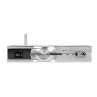
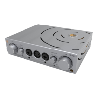
The XLR and RCA outputs on the back oer full preamplier function, but are not switched o if headphones are
connected. Nonetheless, the iCAN Phantom should be used either as preamplier or headphone amplier, as generally
a mixed use setup is not recommended.
The Holographic matrices are tightly integrated into the signal circuit. Not only is there no use of DSP and the
linked AD/DA conversion, there are also no additional active elements.
If disabled, the passive elements (resistors, capacitors and inductors) that form the analogue matrix are completely
removed from the circuit, so the delity of the signal in ‘OFF’ remains unaected.
Design Notes from the AMR/iFi Research & Development department