ifm electronic gmbh • Friedrichstraße 1 • 45128 Essen
18.09.2015
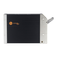
CR0505
Mobile controller
ClassicController
2nd CAN interface
for gateway function
according to SAE J 1939
Programming
according to IEC 61131-3
Operating voltage
10...32 V DC
We reserve the right to make technical alterations without prior notice. CR0505 / page 1
Technical data Controller as black box system
for the implementation of a central or decentralised system design
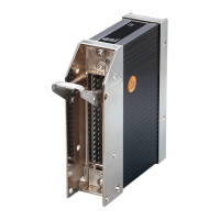
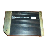
Housing closed, screened metal housing with flange fastening
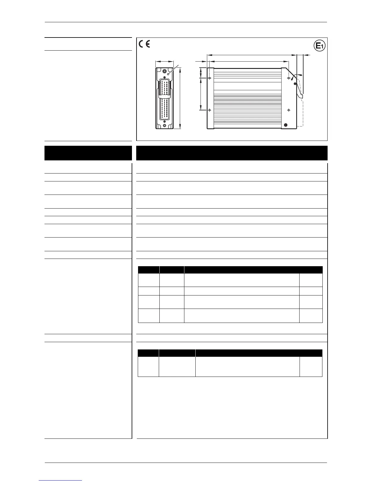
Dimensions (H x W x D) 153 x 226 x 43 mm
Mounting screw connection by means of 4 M5xL screws according to DIN 7500 or DIN 7984
mounting position horizontal or vertical to the mounting wall
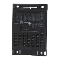
Connection 55-pin connector, latched, protected against reverse polarity, type AMP or Framatome
AMP junior timer contacts, crimp connection 0.5/2.5 mm²
Weight 1.2 kg
Housing / storage temperature – 40...85 °C (depending on the load) / – 40...85 °C
Protection IP 67 (for inserted plug with individually sealed cores e.g. EC2084)
Input/output channels max. 24 (the total number which is available depends
total on the wiring and configuration of the controller)
Inputs max. 24 (corr. to 0 outputs)
possible configurations
Outputs max. 8 (corr. to 16 inputs)
possible configurations
Number Signal Version
8 digital for positive sensor signals, with diagnostic capability B
L
or
analogue 0...10/32 V DC, 0/4...20 mA or ratiometric A
8 digital for positive sensor signals B
L
4 digital for positive sensor signals, with diagnostic capability B
L
or
frequency max. 50 kHz I
L
4 digital for positive/negative sensor signals, with diagnostic capability
*
B
L/H
or
frequency max. 1 kHz I
L
Number Signal Version
8 digital positive switching (High Side), with diagnostic capability B
H
or
PWM PWM frequency 20...250 Hz PWM
or
current-controlled 0,1...4 A PWM
I
Abbreviations
A = analogue
B
H
= binary High Side
B
L
= binary Low Side
FRQ/CYL = frequency inputs
I
H
= pulse High Side
I
L
= pulse Low Side
PWM = pulse width modulation
PWM
I
= current-controlled output
%IWx = IEC address for analogue input
%IX0.xx = IEC address for binary input
%QX0.xx = IEC address for binary output
 Loading...