Do you have a question about the IFM Electronic CR0451 and is the answer not in the manual?
Explains symbols and formats used in the manual for clarity and understanding.
Describes the overall structure and navigation of the manual for effective use.
Provides critical safety information and warnings for handling the device and manual.
Outlines the necessary technical knowledge and prerequisites for users of this manual.
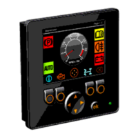
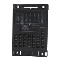
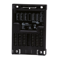
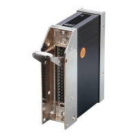
Details the hardware components, features, and specifications of the BasicDisplay.
Provides information on the software environment, CoDeSys version, and system requirements.
Explains the process of configuring the PLC for the ecomatmobile control system.
Describes the different operating states of the ecomatmobile controller and their transitions.
Explains the meaning of different LED colors and flashing frequencies indicating system status.
Covers the management and loading of the operating system onto the controller.
Covers the process of setting up device parameters, including CAN parameters.
Guides users through setting up the programming environment for the device.
Provides initial steps for getting started with the device and programming.
Lists the operational and performance limitations of the device.
Offers tips and best practices for programming with CoDeSys.
Provides recommendations for designing user-friendly interfaces for the device.
Explains fundamental concepts of graphics, colors, and image preparation.
Explains how device power reserves affect bitmap graphic capabilities.
Provides specific details and considerations for using bitmap graphics.
Explains how to use retain variables for data persistence across power cycles or resets.
Provides fundamental information about the Controller Area Network (CAN) bus system.
Details the physical aspects of connecting devices to the CAN network.
Explains how data is exchanged over the CAN bus and the available function blocks.
Introduces function blocks for RAW-CAN communication on OSI layer 2.
Covers the use of CAN units with the SAE J1939 protocol for vehicle communication.
Details CAN POUs (Program Organization Units) for CANopen communication.
Explains how to handle CAN errors and interpret error messages.
Covers functions for reading and writing the device's system time.
Details methods for saving and managing data in the device's memory.
Focuses on controlling data access and performing data checks.
Details functions for controlling the device's status LED.
Covers functions related to managing visualisations on the device.
Lists system flags used for programming, indicating device status and inputs.
Provides an overview of the files and libraries necessary for developing applications.
Defines "Address" as the unique identifier for bus participants.
Defines "Baud" as a unit for data transmission speed.
Defines CAN as a priority-controlled fieldbus system for data transmission.
Defines CAN stack as tasks for CAN data communication.
Defines Category (CAT) in the context of safety-related system classification.
Defines CCF as Common Cause Failure.
Defines CiA as CAN in Automation e.V., a standards body.
Defines CiA DS 304 as a draft standard for CANopen safety.
Defines CiA DS 401 as a draft standard for CAN device profiles.
Defines CiA DS 402 as a draft standard for CAN device profiles for drives.
Defines CiA DS 403 as a draft standard for CAN device profiles for HMI.
Defines CiA DS 404 as a draft standard for CAN device profiles for measurement and control.
Defines CiA DS 405 as a draft standard for interface to programmable controllers.
Defines CiA DS 406 as a draft standard for CAN device profiles for encoders.
Defines CiA DS 407 as a draft standard for CAN application profiles.
Defines Clamp 15 in vehicle electrical systems.
Defines COB-ID as Communication Object Identifier.
Defines CoDeSys as a development tool for IEC 61131-3.
Defines CRC as Cyclic Redundancy Check for data integrity.
Defines Cycle Time as the duration for one PLC program cycle.
Defines DC as Direct Current.
Defines Diagnostic Coverage as a measure of diagnostic effectiveness.
Defines Dither as a PWM signal component for hydraulic valves.
Defines Diversity as a strategy to increase failure safety.
Defines DRAM as Dynamic Random Access Memory.
| Brand | IFM Electronic |
|---|---|
| Model | CR0451 |
| Category | Controller |
| Language | English |