73
ifm System Manual ecomatmobile BasicDisplay (CR0451) V01
CAN in the PDM360 Physical connection of CAN
9.2 Physical connection of CAN
Network structure .........................................................................................................................73
CAN bus level...............................................................................................................................74
Bus cable length...........................................................................................................................75
Wire cross-sections ......................................................................................................................76
1177
The mechanisms of the data transmission and error handling described in the chapters Exchange of
CAN data (→ page 77
) and CAN errors (→ page 207) are directly implemented in the CAN controller.
ISO 11898 describes the physical connection of the individual CAN participants in layer 1.
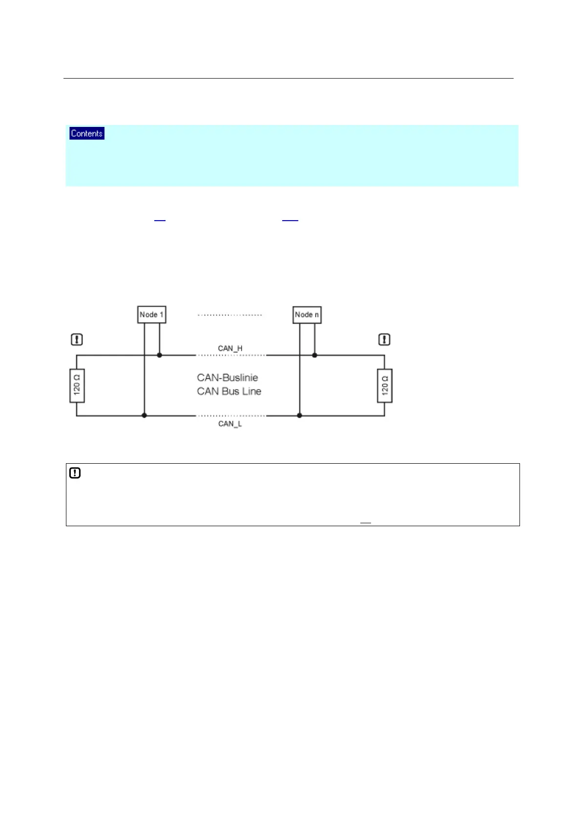
9.2.1 Network structure
1178
The ISO 11898 standard assumes a line structure of the CAN network.
Figure: CAN network line structure
NOTE
The line must be terminated at its two ends using a terminating resistor of 120 to prevent corruption
of the signal quality.
The devices of ifm electronic equipped with a CAN interface have no
terminating resistors.
Spurs
Ideally no spur should lead to the bus participants (node 1 ... node n) because reflections occur
depending on the total cable length and the time-related processes on the bus. To avoid system
errors, spurs to a bus participant (e.g. I/O module) should not exceed a certain length. 2 m spurs
(referred to 125 kbits/s) are considered to be uncritical. The sum of all spurs in the whole system
should not exceed 30 m. In special cases the cable lengths of the line and spurs must be calculated
exactly.