74
ifm System Manual ecomatmobile BasicDisplay (CR0451) V01
CAN in the PDM360 Physical connection of CAN
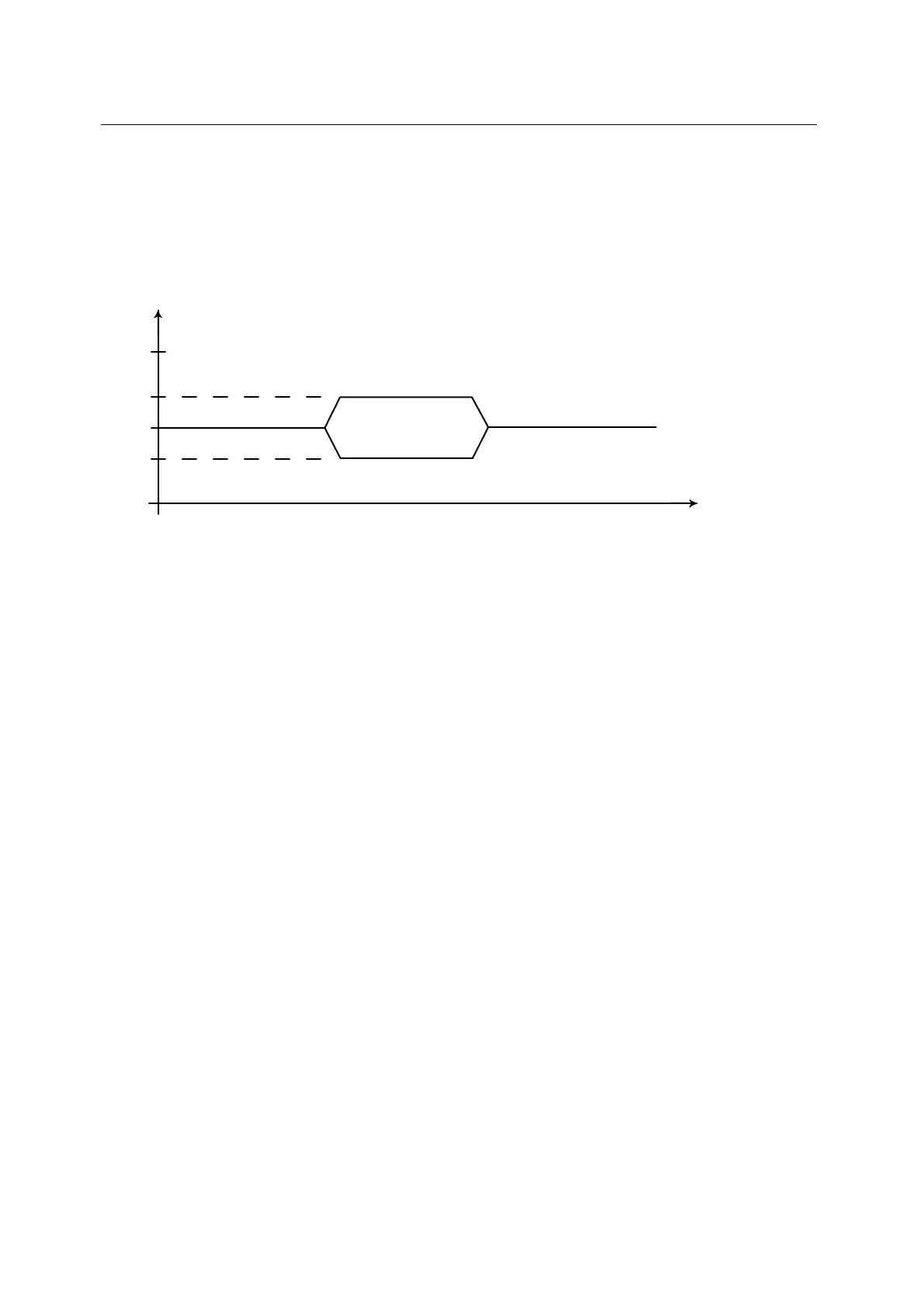
9.2.2 CAN bus level
1179
The CAN bus is in the inactive (recessive) state if the output transistor pairs are switched off in all bus
participants. If at least one transistor pair is switched on, a bit is transferred to the bus. This activates
the bus (dominant). A current flows through the terminating resistors and generates a difference
voltage between the two bus cables. The recessive and dominant states are converted into voltages in
the bus nodes and detected by the receiver circuits.
5 V
3,5 V
2,5 V
1,5 V
0 V
U
t
CAN_H
CAN_L
rezessiv
recessive
rezessiv
recessive
dominant
dominant
Figure: CAN bus level
This differential transmission with common return considerably improves the transmission security.
Noise voltages which interfere with the system externally or shifts of the ground potential influence
both signal cables with the same interference. These influences are therefore not considered when the
difference is formed in the receiver.