Do you have a question about the IFM Electronic SmartController CR2530 and is the answer not in the manual?
Explains symbols used for instructions, reactions, and cross-references.
Details hazard warnings like WARNING, CAUTION, and NOTE with their implications.
General guidelines for device handling, installation, and operation.
Defines the intended audience as authorized persons with electrical qualifications.
Safety precautions for connecting the device to SELV circuits and proper grounding.
Safety considerations regarding high housing temperatures due to internal heating.
Warns against tampering, which voids liability and warranty.
Addresses the device's Class A product status and potential interference.
Outlines safety procedures for welding near the device, including disconnecting power.
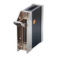
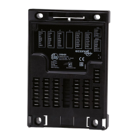
Instructions for fixing the controller using M5 screws with specified torque.
Recommends aligning the controller with cable entries facing downwards.
Specifies that the mounting surface must be flat and avoid torsional forces.
Emphasizes ensuring sufficient heat dissipation and using spacers for sandwich mounting.
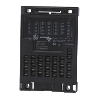
Guidelines for connecting pins as shown in the pin layout and connecting supply/GND.
Importance of connecting the housing to GND for electrical interference protection.
Lists recommended fuses for supply voltage circuits to protect the system.
Best practices for routing cables separately to prevent interference.
Recommendations for operating frequency inputs with screened cables and connecting screens.
Details connection for ground return resistor inputs and ensuring measurement accuracy.
Crucial note about connecting connectors only when power is off (no hot plugging).
Mentions creating application software using the IEC 61131-3 compliant CoDeSys 2.3.
Lists necessary documents like manuals for programming and setup.
Provides detailed specifications on dimensions, weight, voltage, interfaces, and protection ratings.
Explains the status LED colours and their meanings for different operating states.
Lists relevant CE, E1, electrical, climatic, and mechanical test standards the device complies with.
Details specifications for various analog and digital input types, including resolution and resistance.
Provides specifications for digital, PWM, and analog output types, including voltage and current.
Illustrates pin assignments and connectivity for all inputs, outputs, and interfaces.
| Brand | IFM Electronic |
|---|---|
| Model | SmartController CR2530 |
| Category | Controller |
| Language | English |