UK
SmartController CR2530
9
5 Electrical connection
5.1 Wiring
Wiring (→ 7 Technical data)
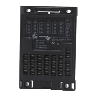
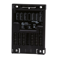
Only connect the connector pins as shown in the pin layout�
Unspecified connector pins remain unconnected�
► Connect all indicated supply cables and GND terminals�
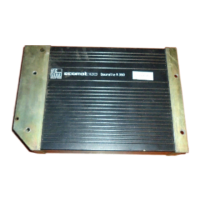
5.2 Ground connection
► To ensure the protection of the device against electrical interference, the
housing must be connected to GND (e�g� to the ground of the vehicle)�
1: Drill holes for ground connection
► Establish a connection between the device and the ground of the vehicle using
M5 screws�
Screws to be used (→ 4.1 Fixing)
5.3 Fuses
► The individual electric circuits must be protected in order to protect the whole
system�
Potential Description Pin no. Fuse
VBB
S
Supply voltage sensors/module 10 ≤ 2 A T
VBB
1
Supply voltage output group 1 19 ≤ 15 A
VBB
2
Supply voltage output group 2 01 ≤ 15 A