7
UK
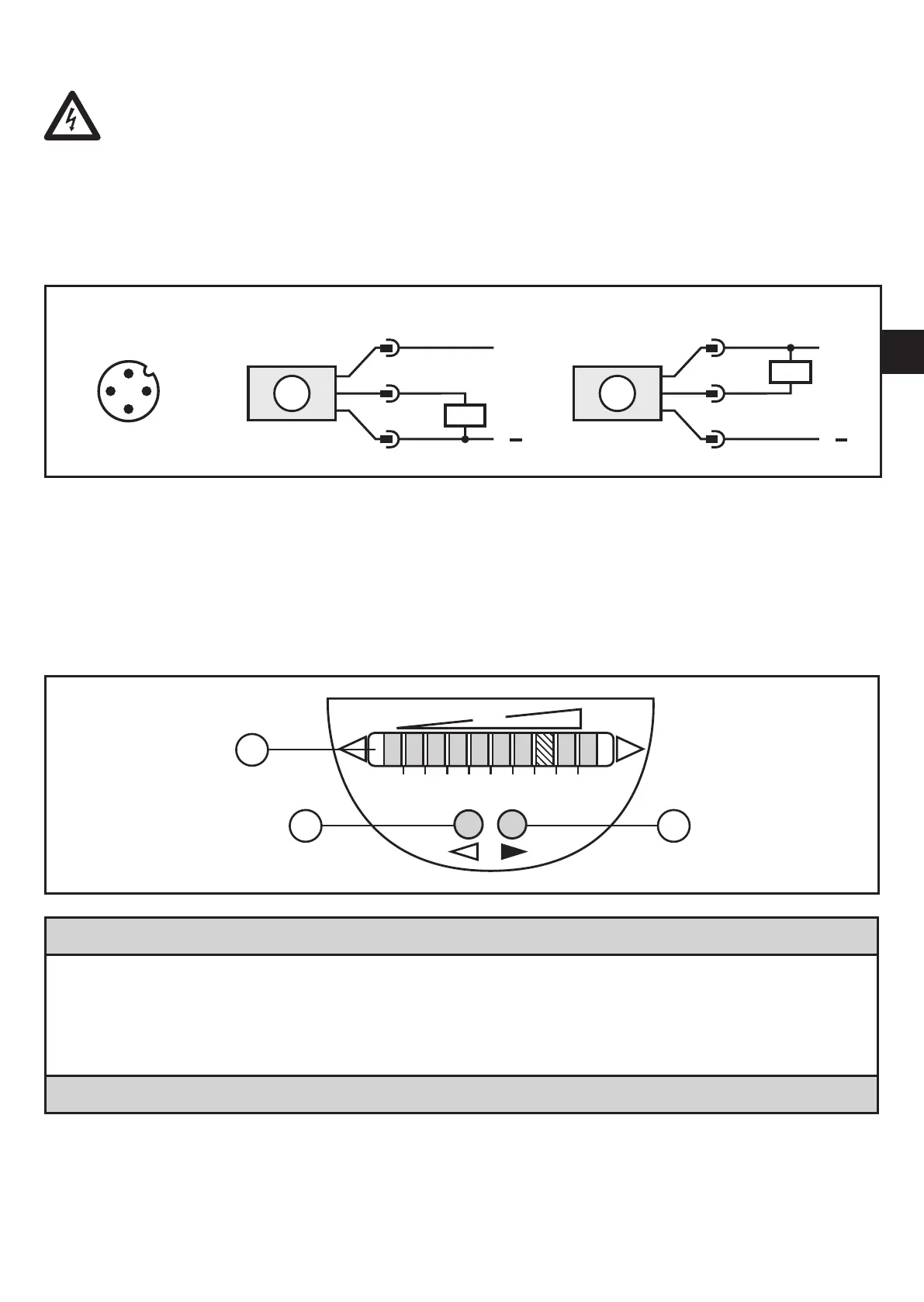
4 Electrical connection
The unit must be connected by a qualified electrician�
The national and international regulations for the installation of electrical
equipment must be adhered to�
Voltage supply to EN 50178, SELV, PELV�
► Disconnect power�
► Connect the unit as follows:
A: SI5000 (positive switching); B: SI5001 (negative switching)
Core colours of ifm sockets:
1 = BN (brown), 3 = BU (blue), 4 = BK (black)
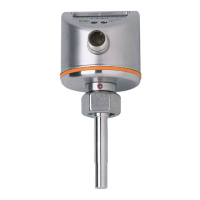
5 Operating and display elements
1: Operation display
• The green LEDs indicate the current flow (the LEDs 0 to 9 represent the range between
no flow and maximum flow)�
• A lighting LED indicates the position of the switch point (orange = output closed, red =
output open)�
2, 3: Setting buttons for adjustment and configuration