Do you have a question about the IFM Electronic O1D100 and is the answer not in the manual?
Details laser protection class 2 and warns against staring into the beam.
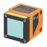
Measures distances, displays values on a 10-segment display, and generates output signals.
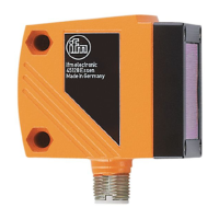
Identifies LEDs, display, and programming buttons with their respective functions.
Details settings for output 1 & 2: normally open, normally closed, and 4-20mA analogue output.
Emphasizes connection by a skilled electrician and adherence to regulations for safety.
Illustrates connection configurations for p-switching and analogue outputs.
Normal operation mode where the unit monitors and generates outputs based on parameters.
Allows reading parameters and values by briefly pressing buttons without changing operation.
Enables setting parameter values by holding the 'Set' button and confirming changes.
Details the sequence for calling parameters, setting values, and confirming changes.
Explains how decreasing a value cycles from maximum to minimum setting.
Recommends selecting the display unit before parameter setting to avoid rounding errors.
Describes how to lock/unlock parameters to prevent unintended adjustments.
Lists common fault codes (++, --, far, near, SC1, SC2, SC) and their meanings.
States the operational lifespan of the product's laser diode.
Defines limit values for output switching status, with SP2 dependent on OU2 settings.
Details settings for output 1 (Hno/Hnc) and output 2 (Hno/Hnc/analogue).
Sets measured values for 4 mA (ASP) and 20 mA (AEP) analogue output, active if OU2 = I.
Provides access to Teach mode (sampling/repeatability) and Extended Functions.
Allows configuring switch-on and switch-off delays for both output 1 and output 2.
Allows selection of display update rates (50-600 ms) and 180° rotation, or deactivation.
Lists available units (mm, m, inch) for displaying measured values and parameters.
Details the button sequence to restore the unit to its original factory configuration.
Enlists the default values for measurement unit, switch points, output configuration, etc.
Explains hysteresis calculation based on repeatability and a safety factor of 1.5.
Provides a step-by-step example of calculating set and reset points for hysteresis.
Presents data on repeatability and accuracy for different distances and remission values at 50 Hz.
Specifies the environmental and operational conditions under which the table values are valid.
Defines the measured value corresponding to the 4 mA analogue output signal.
Defines the measured value corresponding to the 20 mA analogue output signal.
Explains how AEP before ASP creates a falling edge for the analogue output.
Describes the mA signals for values outside the analogue start (ASP) and end (AEP) points.
Shows the current distance measurement on the display.
Allows setting SP1/OU1 and SP2/OU2 for output switching logic.
Allows setting analogue start (ASP) and end (AEP) points for output 2.
Provides access to Teach mode and Extended Functions submenu for advanced settings.
Allows configuring switch-on and switch-off delays for both output 1 and output 2.
Enables selection of display update rates, rotation, or deactivation.
Allows unit selection, signal strength display, and software version check.
Restores the unit to its factory default settings.
Allows setting the sampling rate, which influences the repeatability of measurements.
Allows setting the repeatability, which influences the sampling rate of measurements.
Explains that repeatabilities are selectable based on current conditions and the object.
Indicates when repeatability calculation is in progress ('WAIT' message).
Provides dimensions and labels for physical components like buttons and display.
| Type | Distance sensor |
|---|---|
| Laser protection class | Class 1 |
| Wavelength | 650 nm |
| Protection class | III |
| Sensing range | 0.2...10 m |
| Ambient temperature | -10...60 °C |
| Short-circuit protection | Yes |
| Overload protection | Yes |
| Reverse polarity protection | Yes |
| IP rating | IP67 |
| Connection | M12 connector |
| Product Type | Photoelectric sensor |
| Manufacturer | IFM Electronic |
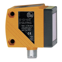
| Model | O1D100 |
| Supply voltage | 18...30 V DC |
| Analogue output | 4...20 mA |