The ifm electronic efectorBOO VKV021 is a vibration sensor designed to detect and evaluate vibration in a system, converting the measured vibration velocity into an analog signal at the current output. Its switching output behavior is determined by two adjustable setting rings.
Function Description:
The core function of the VKV021 is to monitor vibration velocity. When the detected vibration velocity exceeds a user-defined threshold for a specified duration, the sensor activates a switching output. This makes it suitable for applications requiring continuous vibration monitoring and the triggering of actions based on abnormal vibration levels. The sensor provides both an analog current output (4...20 mA) proportional to the vibration velocity and a digital switching output (normally closed).
Important Technical Specifications:
- Measuring Range (Veff): 0...25 mm/s
- Current Output (Iout): 4...20 mA
- Response Delay: 1...60 seconds (adjustable)
- Tightening Torque: 15 Nm
- Process Connection: M8
- Electrical Connection: M12 connector (Pin 1: L+, Pin 2: 4...20 mA, Pin 3: GND, Pin 4: digital output - normally closed)
- Dimensions: Ø27 mm, M12x1 thread, total length 73.1 mm (including M8 process connection), body length 63.7 mm, M8 thread length 11 mm.
Usage Features:
- Installation:
- The sensor should be mounted in a thick housing wall, preferably using a transport thread, to ensure secure installation and proper vibration transmission.
- It is crucial to ensure the correct signal direction during installation.
- A safe vibration transmission is paramount; avoid any elastic intermediate layers that could dampen or distort the vibration signal.
- Tighten the sensor with a torque of 15 Nm to ensure optimal contact and performance.
- Electrical connection must be performed by a qualified electrician in compliance with national and international regulations for electrical equipment installation.
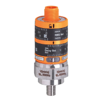
- Settings:
- RMS Set: This setting ring defines the effective value of the switching threshold for vibration velocity. Users can adjust this to set the limit at which vibration is considered excessive.
- Delay Set: This setting ring determines the time in seconds for which the vibration velocity must continuously exceed the RMS Set threshold before the switching output (normally closed pin 4) is activated. This delay helps prevent false triggers from momentary vibration spikes.
- Setting Accuracy: To achieve precise settings, it is recommended to first position the setting rings to their lower end stop value, and then adjust them to the desired value.
- Operating and Display Elements:
- Locking Ring: Secures the setting rings in place after adjustment.
- Setting Rings: Manually adjustable rings for RMS Set and Delay Set.
- LED Green: Indicates the presence of voltage supply, confirming the unit is powered.
- LED Yellow: Illuminates when both the switching threshold (RMS Set) has been exceeded and the defined time delay (Delay Set) has elapsed, indicating an active alarm condition.
- Switching Output Behavior:
- The time delay begins when the defined switching threshold is exceeded.
- The time delay is canceled if the vibration value falls below the switching threshold before the full delay period elapses (without triggering a switch-off).
- The switch-off (activation of the digital output) is triggered only when the switching threshold is continuously exceeded for the entire duration of the set time delay.
Maintenance Features:
- Maintenance-Free Operation: The VKV021 is designed for maintenance-free operation, reducing the need for regular checks or servicing.
- No Repair Capability: The unit is not designed to be repaired. In case of malfunction, replacement is necessary.
- Disposal: At the end of its service life, the unit must be disposed of in an environmentally friendly manner, adhering to all applicable national regulations for electronic waste.
The VKV021 is a robust and reliable sensor for industrial vibration monitoring, providing clear indications and configurable thresholds to protect machinery and ensure operational safety. Its compact design and straightforward interface make it suitable for integration into various industrial applications. For detailed technical data and further information, users are directed to the ifm electronic website.