EasyManua.ls Logo

IFM Electronic SA 00 Series - User Manual

IFM Electronic SA 00 Series
40 pages
Print Icon
To Next Page IconTo Next Page
Loading...
Operating instructions
Flow sensor
SAxx00
SAxx10
SAxx30
SAxx40
80260078 / 00 05 / 2018
UK

Table of Contents

Questions and Answers

  • B
    Bailey SimsAug 17, 2025
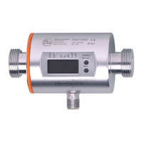
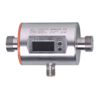
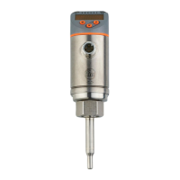
    What to do if there is a short circuit in OUT1 and OUT2 of IFM Electronic Accessories?
    • M
      Michelle TorresAug 18, 2025
      If you experience a short circuit in both OUT1 and OUT2 of your IFM Electronic Accessories, inspect the switching outputs OU1 and OUT2 for short-circuits or excessive current.
  • W
    woodsmariaAug 20, 2025
    What to do if there is a short circuit in OUT1 of IFM Electronic Accessories?
    • P
      Peter CarrollAug 20, 2025
      If you encounter a short circuit in OUT1 of your IFM Electronic Accessories, check the switching output OUT1 for a short-circuit or excessive current.
  • M
    Mary YangAug 22, 2025
    What to do if there is a short circuit in OUT2 of IFM Electronic Accessories?
    • C
      Courtney EspinozaAug 23, 2025
      If you encounter a short circuit in OUT2 of your IFM Electronic Accessories, check the switching output OUT2 for a short-circuit or excessive current.
  • B
    Brandon JonesAug 26, 2025
    How to troubleshoot a faulty IFM Electronic Accessories unit?
    • J
      John TaylorAug 26, 2025
      If your IFM Electronic Accessories unit is faulty or malfunctioning, consider the following: * Replace the unit. * Check the supply voltage. * Change the setting [diS].
  • H
    Hannah GarciaAug 27, 2025
    What to do if setting pushbuttons on IFM Electronic Accessories are locked?
    • M
      megan30Aug 27, 2025
      If the setting pushbuttons on your IFM Electronic Accessories unit are locked and parameter changes are rejected, unlock the unit.
  • M
    Monica TuckerAug 30, 2025
    What to do if the supply voltage is too low for IFM Electronic Accessories?
    • M
      Maria WalshAug 30, 2025
      If the supply voltage is too low for your IFM Electronic Accessories, check the supply voltage and change the setting [diS].
  • G
    granttoddSep 1, 2025
    What to do if setting buttons are locked on IFM Electronic Accessories due to IO-Link communication?
    • K
      Kristine JonesSep 2, 2025
      If the setting buttons on your IFM Electronic Accessories unit are temporarily locked because parameter setting via IO-Link communication is active, finish parameter setting via IO-Link communication.
  • M
    Meghan AlexanderSep 4, 2025
    How to unlock setting buttons on IFM Electronic Accessories locked via parameter software?
    • M
      markzhangSep 4, 2025
      If the setting buttons are locked via parameter software and parameter change is rejected on your IFM Electronic Accessories, unlock the unit via the IO-Link interface using the parameter setting software.
  • M
    michelle82Sep 6, 2025
    What to do if IFM Electronic Accessories measured value is above the display range?
    • C
      cynthia20Sep 7, 2025
      If the measured value is above the display range (greater than 120% of MEW) for your IFM Electronic Accessories, check the flow range or temperature range and repeat high-flow adjustment.
  • S
    Sarah ReyesSep 9, 2025
    What to do if IFM Electronic Accessories temperature value is below the display range?
    • J
      Jason TuckerSep 9, 2025
      If the measured temperature value is below the display range (less than -20% MEW) for your IFM Electronic Accessories, check the temperature range and repeat low-flow adjustment.

Summary

Safety Instructions

Custom Flow Calibration

Customer-Specific Calibration (CGA)

Adjusts sensor output and display via a calibration factor for application.

Mounting and Installation Guidelines

Installation Position and Sensor Placement

Sensor Installation Position

Details sensor placement, immersion depth, and tightening torques.

Electrical Connection Procedures

Operating and Display Elements

Parameter Setting Procedures

General Parameter Setting Guide

Step-by-step instructions for navigating and changing parameters.

Volumetric Flow Monitoring Setup

Define Operating Mode and Pipe Diameter

Sets operating mode (REL, LIQU, GAS) and defines internal pipe diameter.

Flow Output Signal Configuration

Limit Value Monitoring for Flow

Configures switching signals for flow limit values for OUT1 and OUT2.

Frequency Signal Setup for Flow

Sets up frequency output based on flow values for OUT1 and OUT2.

Flow Adjustment and Analogue Output

Analogue Output for Flow

Configures the 4-20mA analogue output for flow measurement on OUT2.

Carrying out Flow Adjustment

Guides on performing high-flow and low-flow adjustments.

Temperature Monitoring Setup

Limit Value Monitoring for Temperature

Configures limit value switching signals for temperature on OUT2.

Frequency Signal for Temperature

Sets up frequency output based on temperature values for OUT2.

Analogue Output for Temperature

Configures the 4-20mA analogue output for temperature on OUT2.

Output Logic and Fault Handling

Fault Condition Output Status

Defines output behaviour (ON/OFF/OU) during fault conditions.

Service Functions and Operation

Resetting Parameters to Factory Settings

Resets all parameters to their original factory default settings.

Parameter Access and Troubleshooting

IFM Electronic SA 00 Series Specifications

General IconGeneral
BrandIFM Electronic
ModelSA 00 Series
CategoryAccessories
LanguageEnglish

Related product manuals