Do you have a question about the IFM Electronic SM6000 and is the answer not in the manual?
Explains symbols used in the document, such as instruction, reaction, cross-references, and important notes.
Describes signal processing, current value display, and output signal generation based on parameter settings.
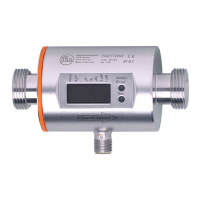
Explains the principle of measuring volumetric flow via a magnetic field and its proportional signal voltage.
Details the totalizer function, summing volumetric flow since the last reset, considering flow direction.
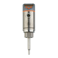
Covers monitoring medium temperature and outputting it as a switching or analogue signal.
Explains switching functions for volumetric flow or temperature, including hysteresis and window modes.
Describes analogue output functions for volumetric flow or temperature, specifying start and end points for signals.
Details the start-up delay function, its activation, and its effect on switching signals for volumetric flow.
Provides guidelines for installing the unit in pipes, emphasizing complete filling and proper pipe lengths to avoid disturbances.
Explains the use of adapters for pipe installation, including order numbers and tightening procedures.
Advises on protecting the unit from high medium temperatures and contact with hazardous substances.
Presents a visual overview of the device's menu structure, illustrating parameter organization and navigation.
Provides detailed definitions for each parameter in the menu, clarifying their purpose and settings.
Outlines the fundamental three-step process for setting any parameter: selection, value adjustment, and confirmation.
Details parameter configurations specific to monitoring volumetric flow, including limit values and analogue signal scaling.
Explains parameter settings for monitoring consumed quantities, focusing on pulse output and preset meter functions.
Covers parameter settings for monitoring temperature, focusing on limit value configurations.
Describes optional user-configurable settings such as units, display options, output logic, and damping.
Details service functions like retrieving minimum/maximum values and performing factory resets.
Explains how to set the preset meter or pulse value, detailing the input process and available ranges.
Guides on how to retrieve and view the currently configured parameters and their values.
Explains how to switch between different measurement units displayed in the active operating mode.
Lists and explains various error codes displayed by the unit, indicating faults or operational issues.
Provides general operating advice, including avoiding deposits and proper handling during high temperatures.
Details the valid minimum and maximum ranges for setting various parameters like flow, temperature, and pulse values.
| Brand | IFM Electronic |
|---|---|
| Model | SM6000 |
| Category | Accessories |
| Language | English |