Do you have a question about the IFM Electronic LR3000 and is the answer not in the manual?
Explanation of symbols used in the manual for instructions, reactions, and notes.
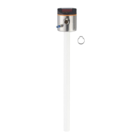
Details the use of the unit with a single rod probe, including installation requirements.
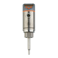
Explains the operation with a coaxial probe, suitable for various media types.
Lists suitable media, examples, and conditions causing measurement errors.
Explains the guided wave radar technology used for level measurement.
Highlights key features like easy setup, display functions, analogue and switching outputs.
General information on the IO-Link communication interface for data access and parameter settings.
Guidelines for selecting an optimal installation location and environment.
Instructions for installing the probe rod and coaxial pipe onto the sensor unit.
Guide on how to shorten the probe rod and coaxial pipe for tank adaptation.
Procedures for installing the unit in various tank types with a single probe.
Steps for installing the unit with a coaxial probe in the tank.
How to align and rotate the sensor housing after installation.
Visual representation of the menu hierarchy and available parameters.
Detailed explanation of each menu item and its function.
Describes the general steps for setting parameters and navigating menu levels.
Covers initial setup for probe length, medium, and probe type.
How to set display units, type, and offset for accurate level indication.
Details setting output functions, switching limits, delays, and analogue scaling.
Procedures for resetting parameters and modifying basic settings.
Explains unit indicators for level, status, and faults.
Lists possible error codes, their causes, and recommended corrective actions.
Describes the output behavior during initialization, normal operation, and fault conditions.
Details the configurable ranges for probe length, offset, switching limits, and analogue points.
| Brand | IFM Electronic |
|---|---|
| Model | LR3000 |
| Category | Accessories |
| Language | English |