Do you have a question about the IFM Electronic PN7000 and is the answer not in the manual?
Defines symbols used in the document for instructions, reactions, cross-references, and important notes.
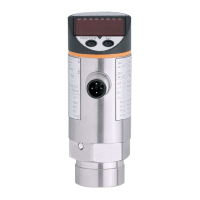
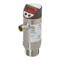
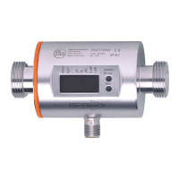
Details the product's monitoring capabilities, application types, and lists specific models with their measuring ranges.
Explains unit display, output signals (switching, diagnostic), and IO-Link communication.
Details how output switching works based on set limits, including hysteresis and window functions.
Describes the diagnostic capabilities of Output 2, activated when [OU2] is set to [dESI].
Presents a visual representation of the device's internal menu hierarchy and parameter flow.
Provides detailed definitions for each parameter found within the device's menu system.
Details the three-step process for selecting, modifying, and acknowledging parameter values.
Explains how to set display units, update rates, and orientation for the device screen.
Covers the configuration of output functions and switching limits for the device's outputs.
Details how to configure the output function for OUT1 and OUT2 (hysteresis/window, open/closed).
Explains how to set the upper (SPx) and lower (rPx) switching limits for the outputs.
Covers optional user configurations like time delays, output logic, and damping for switching signals.
Describes how to read minimum/maximum values and reset all parameters to factory defaults.
Explains how to view the currently set parameter values displayed on the unit.
Lists and explains fault codes (OL, UL, SC1, SC2, SC, Err) indicating operational issues.
Provides detailed tables of minimum and maximum setting ranges for various parameters across different product models.
| Brand | IFM Electronic |
|---|---|
| Model | PN7000 |
| Category | Accessories |
| Language | English |