14
Device-specific information
You will find the IODDs necessary for the configuration of the IO-Link unit and
detailed information about process data structure, diagnostic information and
parameter addresses at www�ifm�com/gb/io-link�
Parameter setting tools
You will find all necessary information about the required IO-Link hardware and
software at www�ifm�com/gb/io-link�
6 Installation
6.1 Installation location / environment
• Vertical installation from the top is preferred�
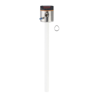
6.1.1 Unit with single probe
• For a safe function, the unit requires a launching plate (→ 6.4).
• For optimum operation the unit is to be installed as near as possible to the tank
wall� Distance between the rod and the tank wall: minimum 40 mm, maximum
300 mm�
• The following minimum distances between the rod and tank walls, objects in
the tank (B), tank bottom and other level sensors must be adhered to:
50mm
10mm
100mm
B
40mm
• For tank walls which are not straight, steps, supports or other structures in the
tank a distance of 50 mm to the tank wall must be adhered to�