23
UK
► Arrange for a bore hole in the tank lid� It must have a minimum diameter (d) to
enable sufficient transfer of the measured signal to the probe (fig� 6-10)� The
diameter depends on the wall thickness of the tank lid:
Wall thickness [mm] 1���5 5���8 8���11
Bore hole diameter [mm] 35 45 55
► Install the flange plate with the flat surface showing to the tank and fix it with
appropriate screws�
A seal (B in fig� 6-11) can be inserted between flange plate and tank� Some
flange plates are supplied with a seal�
► Ensure cleanness and evenness of the sealing areas, especially if the tank is
under pressure� Tighten the fixing screws sufficiently�
► Screw the unit into the flange plate using the process connection and tighten
firmly�
► Make sure that the supplied sensor seal (A in fig� 6-11) is correctly positioned�
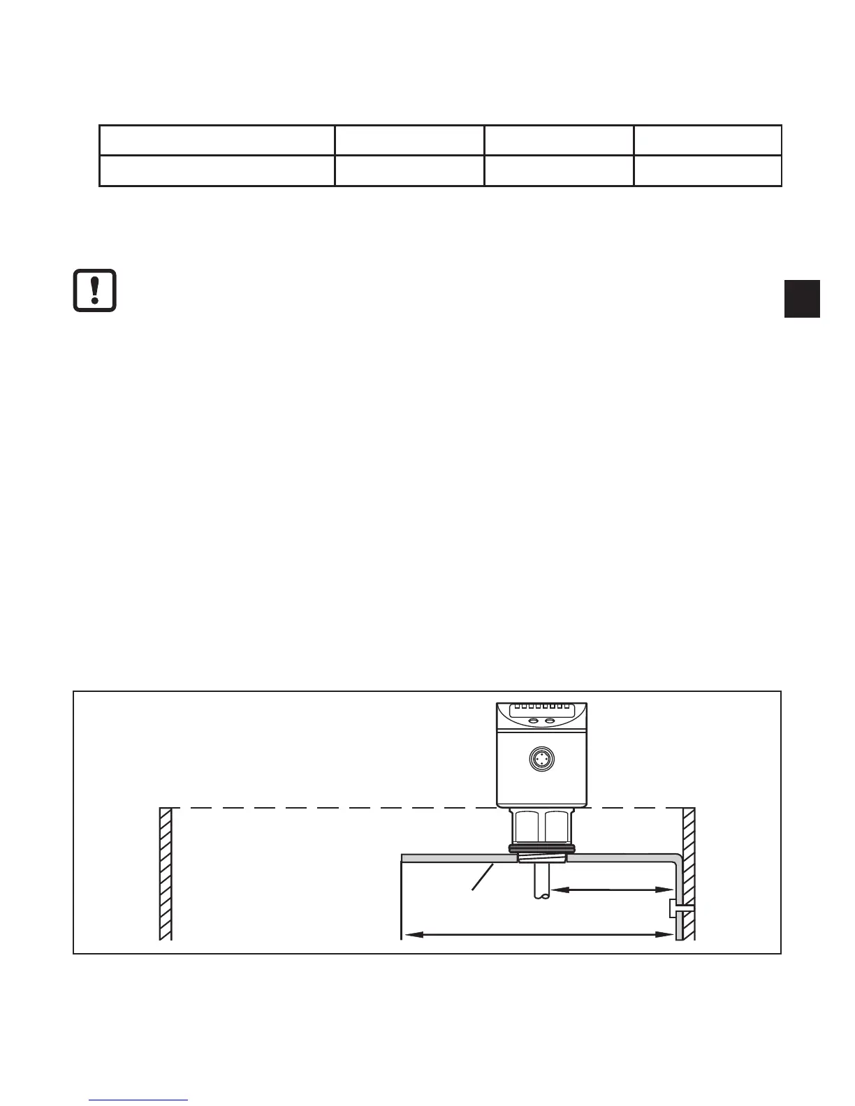
6.4.3 Installation in open tanks
► For installation in open tanks, use a metal fixture to install the unit� It serves
as a launching plate (R); minimum size: 150 x 150 mm for a square fixture,
150 mm diameter for a circular fixture�
► If possible, mount the unit in the middle of the fixture� The distance D2 must not
be below 40 mm, higher for probe lengths > 70 cm and in case of heavy soiling
(→ 6.1.1):
D2
150 mm
R
► The lower edge of the process connection should be flush with the installation
environment (see fig� 6-7)�
► Avoid non-flush installation (see fig� 6-8)�