12
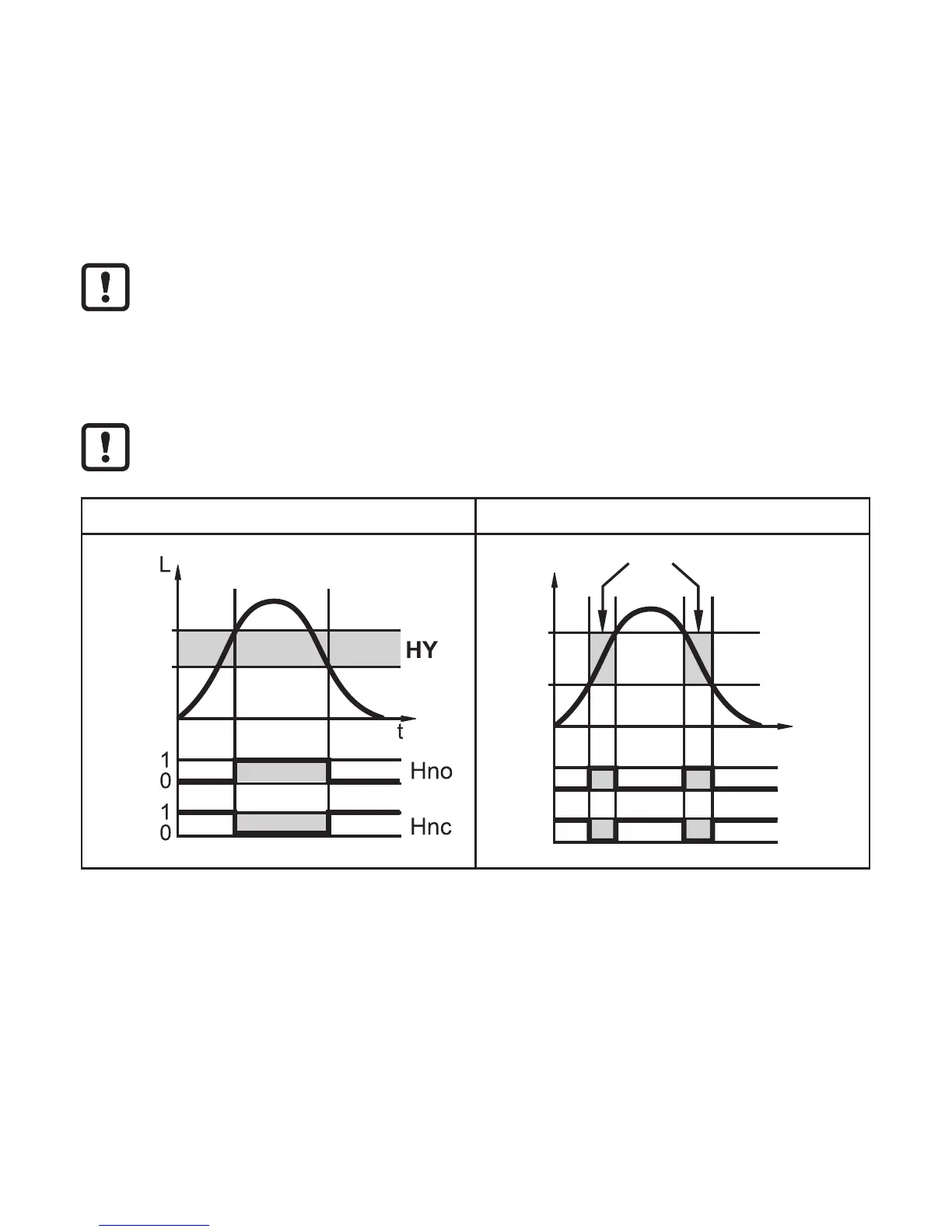
5.2.4 Switching functions
The unit signals via the switching output (OUT1) that a set limit value has been
reached or that the level is below the limit value� For each output the following
switching functions can be selected:
• Hysteresis function / normally open (fig� 5-3): [OU1] = [Hno]�
• Hysteresis function / normally closed (fig� 5�3): [OU1] = [Hnc]�
First the set point (SP1) is set, then the reset point (rP1) with the requested
difference�
• Window function / normally open (fig� 5-4): [OU1] = [Fno]�
• Window function / normally closed (fig� 5-4): [OU1] = [Fnc]�
The width of the window can be set by means of the difference between
FH1 and FL1� FH1 = upper value, FL1 = lower value�
Fig. 5-3 Fig. 5-4
SP1
rP1
t
L
FH1
FL1
1
0
1
0
FE
Fno
Fnc
L = level; HY = hysteresis; FE = window
• For the switching output a switch-off delay of max� 60 s can be set (e�g� for
especially long pump cycles)�
5.2.5 Offset for indicating the real level in the tank
The zone between tank bottom and lower edge of the probe can be entered as
offset value [OFS]� So display and switch points refer to the actual level�