37
UK
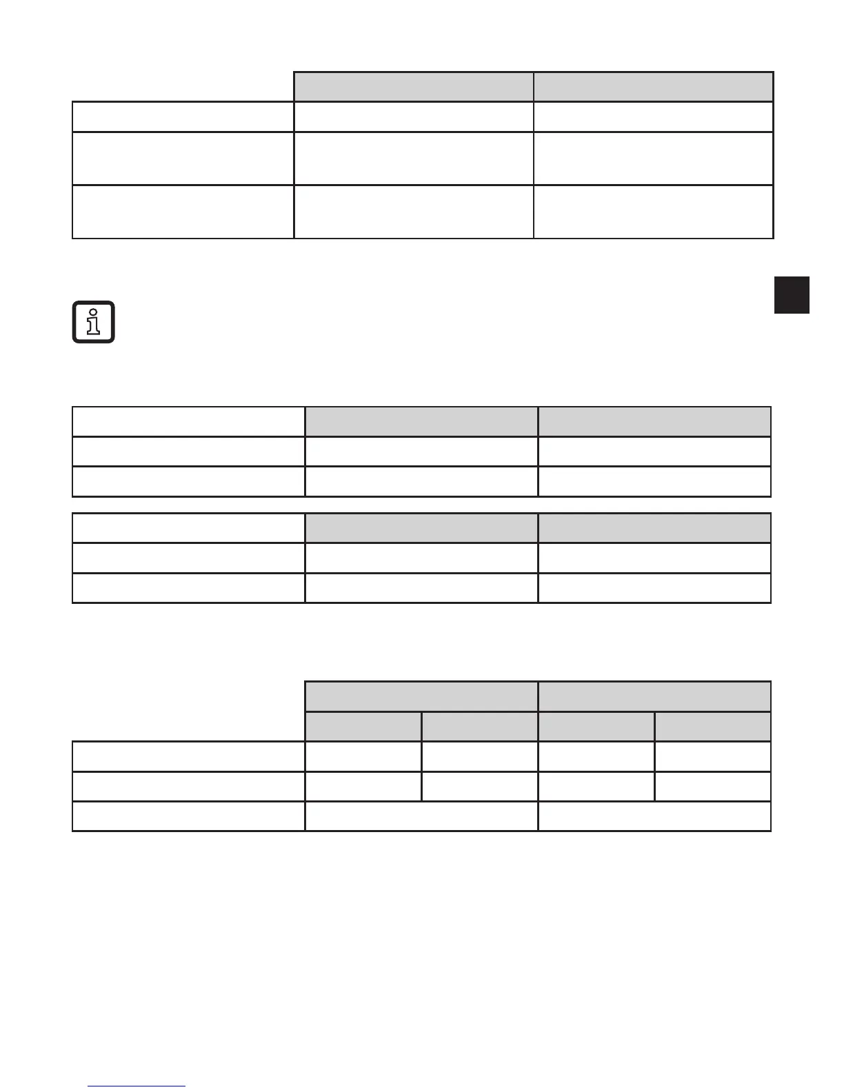
11.5 Output response in different operating states
OUT1 OUT2
Initialisation OFF OFF
Normal operation
according to the level and
OU1 setting
according to the level and
OU2 setting
Fault (E�0xx)
OFF for FOU1 = OFF;
ON for FOU1 = on
4 mA / 0 V for FOU2 = OFF
20 mA / 10 V for FOU2 = on
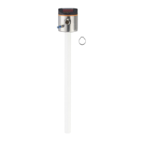
12 Technical data and scale drawing
Technical data and scale drawing at www�ifm�com�
12.1 Setting ranges
[LEnG] cm inch
Setting range 10���160 4�0���63
Step increment 0�5 0�2
[OFS] cm inch
Setting range 0���100 0���39�4
Step increment 0�5 0�2
The setting ranges for the switching limits (SP1, rP1, FH1, FL1) depend on the
probe length (L)� In general the following applies:
cm inch
min max min max
SP1 / FH1 1�5 (3�5) L - 3 0�6 (1�4) L - 1�2
rP1 / FL1 1�0 (3�0) L - 3�5 0�4 (1�2) L - 1�4
Step increment 0�5 0�2
The values apply if [OFS] = 0� The values in brackets apply to the setting
[MEdI] = [LOW] (setting for the detection of oils and oil-based media)�
• rP1 is always lower than SP1. If the value for SP1 is reduced to a value ≤ rP1 the position
of rP1 also shifts�
• If rP1 and SP1 are close together (about 3 x step increment), rP1 is changed automatically
when increasing SP1�
• If there is a greater difference between rP1 and SP1, rP1 maintains the set value even if
SP1 is increased�