Do you have a question about the IFM Electronic O1D155 and is the answer not in the manual?
Explains instructional symbols and notes like Instruction, Reaction, Cross-reference, Important note, and Information.
Explains the WARNING symbol indicating potential for serious personal injury.
Lists applications including measurement range, background suppression, display, and output signals.
Keeps the switching state stable with measured value variations around the set point.
Enables monitoring of a defined acceptable range for object recognition.
Outputs an analogue signal proportional to the measured distance.
How to temporarily switch off the laser for safety and maintenance purposes.
Specifies measuring range, unambiguity range, and advice on object positioning.
Lists available mounting accessories and their corresponding part numbers.
Explains compatibility and connection methods with IO-Link masters (port class A and B).
Provides a visual overview of the device's menu hierarchy.
Details device parameters like output functions, analogue signals, timing, and display settings.
Describes the normal operating mode, monitoring function, and output signals.
Explains how to view parameters and set values on the display.
Describes how to display and interpret object reflectivity.
Refers to the general process of setting parameter values.
General procedures for setting parameters, including value and unit selection.
Step-by-step guide to changing parameter values using the device buttons.
Instructions on how to navigate between different menu levels.
How to lock and unlock the unit to prevent accidental parameter changes.
Covers essential configurations like display unit selection and output functions.
How to choose the unit of measurement (mm, m, inch) for parameters.
How to configure display update rates and modes.
How to set the switching functions (hysteresis, window) for output 1.
Explains the hysteresis function and its set/reset points.
How to set the switch point for the OUT1 hysteresis function.
Explains the window function for object recognition.
How to set the near and far switch points for OUT1 window function.
How to set switching functions or analogue signals for output 2.
How to set the switch point for the OUT2 hysteresis function.
How to set near and far switch points for OUT2 window function.
How to scale the analogue output (4-20mA or 0-10V).
Explains how to configure sampling rate and repeatability.
How to set the sampling rate for measurement updates.
How to set the repeatability value.
Provides tables for repeatability and accuracy at different sampling rates.
Covers advanced functions like delays, damping, and reset.
How to set switch-on and switch-off delays for outputs.
How to set fault suppression time for outputs and analogue signals.
How to restore the device to its default factory settings.
How to view the installed software version.
Overview of the IO-Link interface and its capabilities.
Where to find IODDs and detailed device information.
Information on required IO-Link hardware and software.
IO-Link related extended functions and measured data.
Details available teach functions via IO-Link.
How object reflectivity is provided via IO-Link.
Table detailing possible causes and display indications for faults.
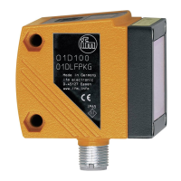
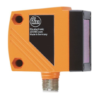
This document describes the O1D155 optical distance sensor, a device designed for precise distance measurement and object detection.
The O1D155 operates as an optical distance sensor, capable of measuring distances between 0.3 and 6 meters. It incorporates a background suppression feature that effectively ignores objects beyond a range of 6 to 100 meters, ensuring accurate readings within the desired sensing area. The sensor provides two configurable output signals based on the set output functions, allowing for flexible integration into various applications.
The sensor offers several output functions:
For safety and maintenance, the laser of the unit can be temporarily switched off via an input on pin 5. A "Low" signal or no connection keeps the laser "On," while a "High" signal switches it "Off."
The unit is compatible with IO-Link master port class A (type A). For operation with IO-Link master port class B (type B), specific wiring configurations are required due to the shared supply voltage on pins 2 and 5.
The O1D155 features a 10-segment display that shows the measured value. Operating and display elements include:
The sensor operates in several modes:
Parameter setting involves selecting the display unit first to avoid rounding errors. Parameters are selected using [MODE/ENTER], values are set using [SET] (pressed and held to flash, then incremented by single presses), and confirmed with [MODE/ENTER]. The unit can be electronically locked to prevent unintentional settings.
Extended functions include:
IO-Link functionality provides direct access to sensor values and parameters, allowing for configuration during operation. It also supports extended functions like "Teach on background" and "Two-point teaching," detailed in the IODD (IO-Link Device Description). Object reflectivity is provided via the display and as a process data value, useful for detecting sensor soiling.
The O1D155 is designed for reliable operation with minimal maintenance.
| Wavelength | 650 nm |
|---|---|
| Housing material | Plastic |
| Lens material | PMMA |
| Protection | Reverse polarity protection |
| Light source | Laser |
| Laser protection class | 2 (IEC 60825-1) |
| Supply voltage | 10-30 V DC |
| Operating temperature | -25 to +60 °C |
| Storage temperature | -40°C to +70°C |