8
6 Electrical connection
The unit must be connected by a qualified electrician�
► The national and international regulations for the installation of electrical
equipment must be adhered to�
► Ensure voltage supply according to EN 50178, SELV, PELV�
O1D155: cULus, Supply Class 2
► Disconnect power�
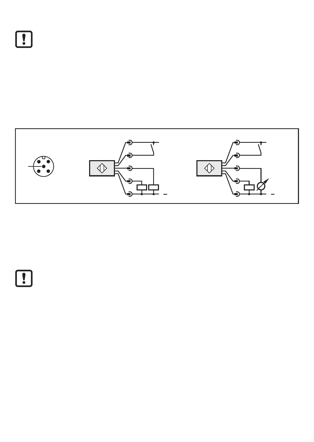
► Connect the unit as follows:
O1D155 PNP
5
EPS Source
Product Scale Drawing
Frame Size: 36 mm x 75 mm
AN_i_1707_G Original Scale Drawing (MTD)
L
+
L
5
4
3
2
IN
L
L
5
4
3
2
IN
2: OUT2
4: OUT1
2: OUT2
4: OUT1
L
+
L
5
1
4
3
2
IN
L
+
L
5
1
4
3
2
IN
2: OUT2
4: OUT1
2: OUT2
4: OUT1
Core colours of ifm sockets:
1 = BN (brown), 2 = WH (white), 3 = BU (blue), 4 = BK (black), 5 = GR (grey)�
6.1 Operation with IO-Link master
The unit is compatible with IO-Link master port class A (type A)�
For operation with IO-Link master port class B (type B) observe the following:
As a standard, the unit is not compatible with master port class B (type B)�
Pin 2 (OU2) and pin 5 (IN1) are used for manufacturer-specific functions�
That means that the main supply voltage of the unit and the additional
voltage supply (master port class B on pins 2/5) are not electrically isolated�
With the following configurations the unit can be used with master port class B:
• Connect unit and IO-Link master via 3 wires: Connect pins 1, 3 and 4 of the
unit with the IO-Link master (do not connect pins 2 and 5)�
• Connect unit and IO-Link master via 4 wires: Deactivate pin 2 (OU2) via
IO-Link (setting OU2 = "off") and connect pins 1, 2, 3 and 4 of the unit with the
IO-Link master (do not connect pin 5)�