6
6 Electrical connection
The unit must be connected by a qualified electrician.
The national and international regulations for the installation of electrical
equipment must be adhered to.
Voltage supply to EN 50178, SELV, PELV.
Disconnect power. ►
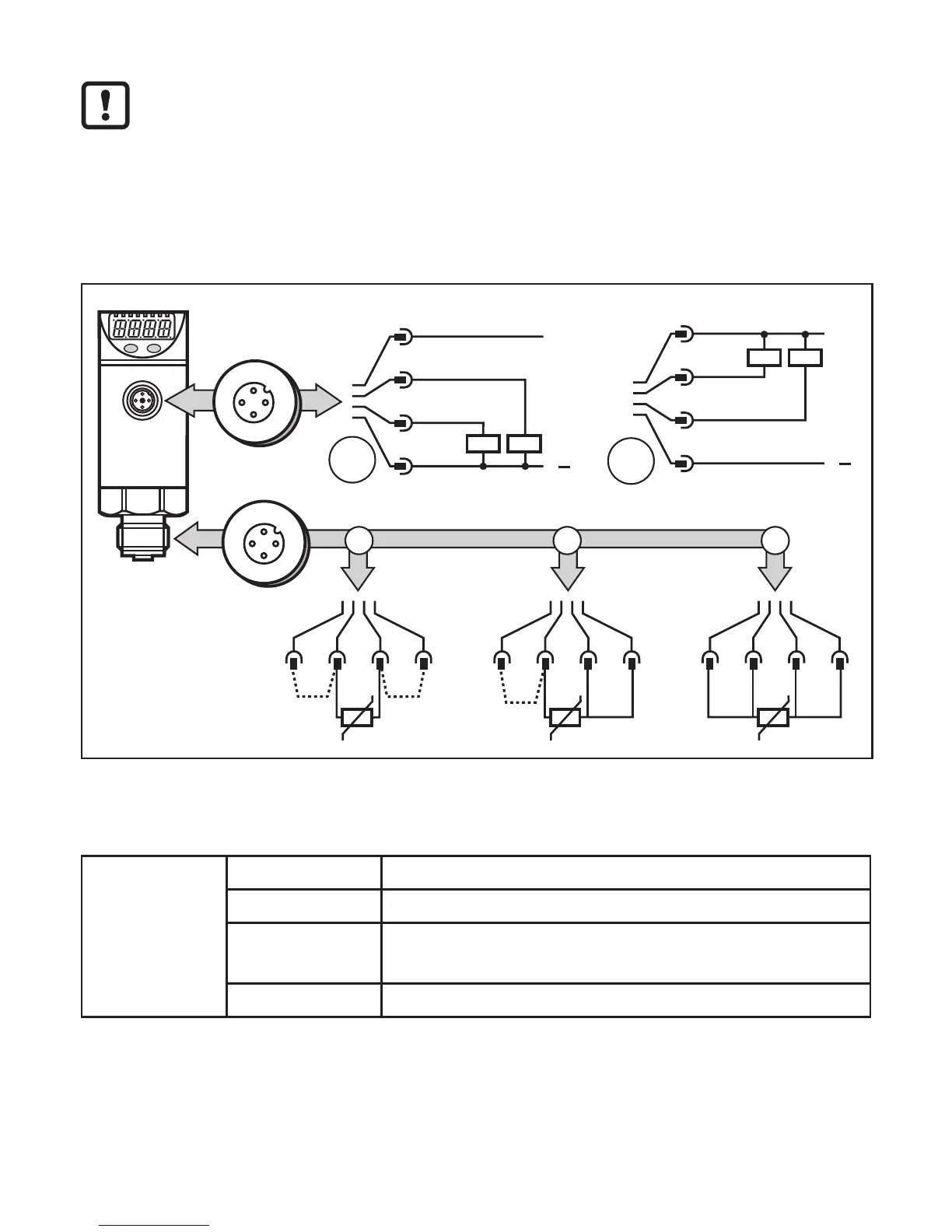
Connect the unit as follows: ►
1: two-wire sensor
2: three-wire sensor
3: four-wire sensor
connection for
voltage supply
and output
signals
Pin 1 Ub+
Pin 3 Ub-
Pin 4 (OUT1)
Binary switching output temperature monitoring.•
Data channel for bidirectional communication.•
Pin 2 (OUT2) Binary switching output temperature monitoring.•