7
UK
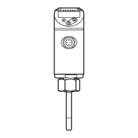
connection for
temperature
sensor
2-wire sensor
Menu setting: Mmod = 4w, links between 1 / 2 and 3
/ 4.
A wiring fault can be corrected in the menu COF.
3-wire sensor
Menu setting: Mmod = 3w, link between 1 / 2.
Themaximumcableresistanceof10Ωpercoremust
not be exceeded (this corresponds to a cable length of
approx. 80 m for a wire cross-section of 0.14mm²).
4-wire sensor Menu setting: Mmod = 4w.
Core colours of ifm sockets:
1 = BN (brown), 2 = WH (white), 3 = BU (blue), 4 = BK (black)
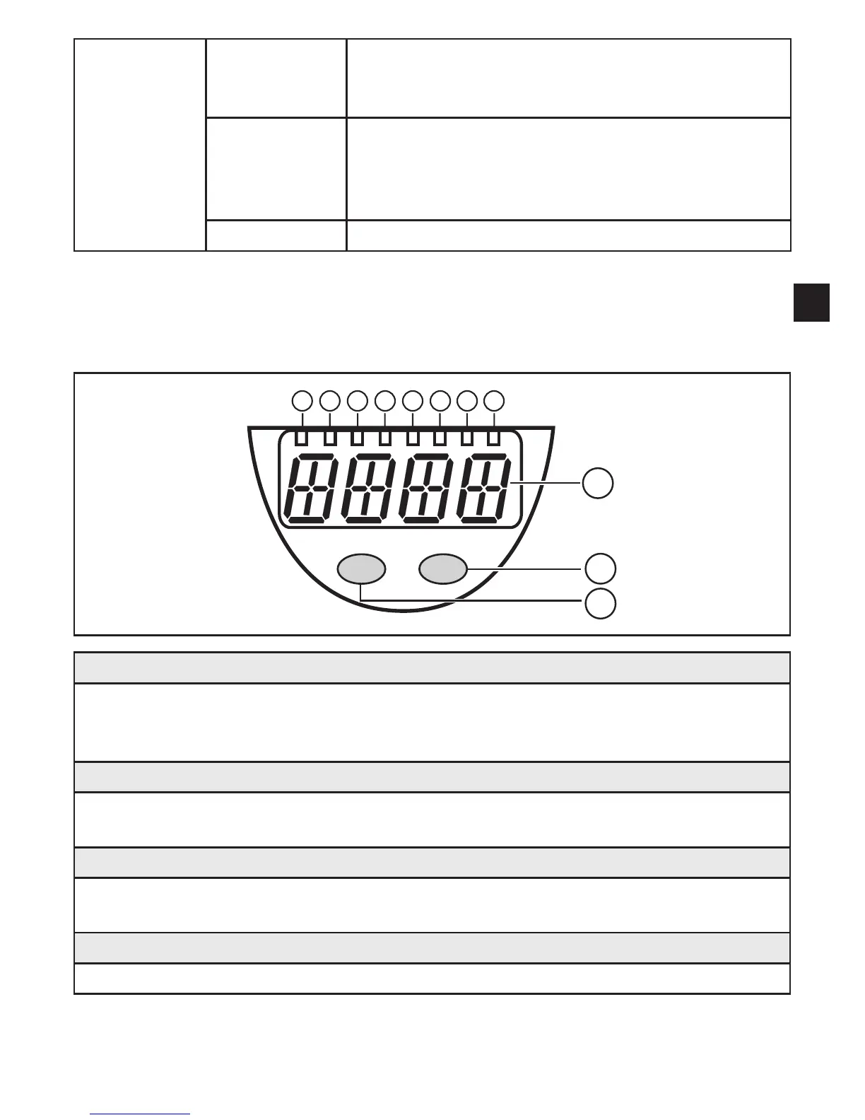
7 Operating and display elements
1 to 8: Indicator LEDs
LED 1: Current temperature in °C. -
LED 2: Current temperature in °F. -
LED 7, LED 8 = switching state of the corresponding output. -
9: Alphanumeric display, 4 digits
Display of the current system temperature. -
Indication of the parameters and parameter values. -
10: Set button
Setting of the parameter values (scrolling by holding pressed; incrementally by pressing -
once).
11: Mode/Enter button
Selection of the parameters and acknowledgement of the parameter values. -