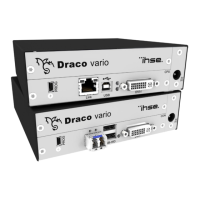
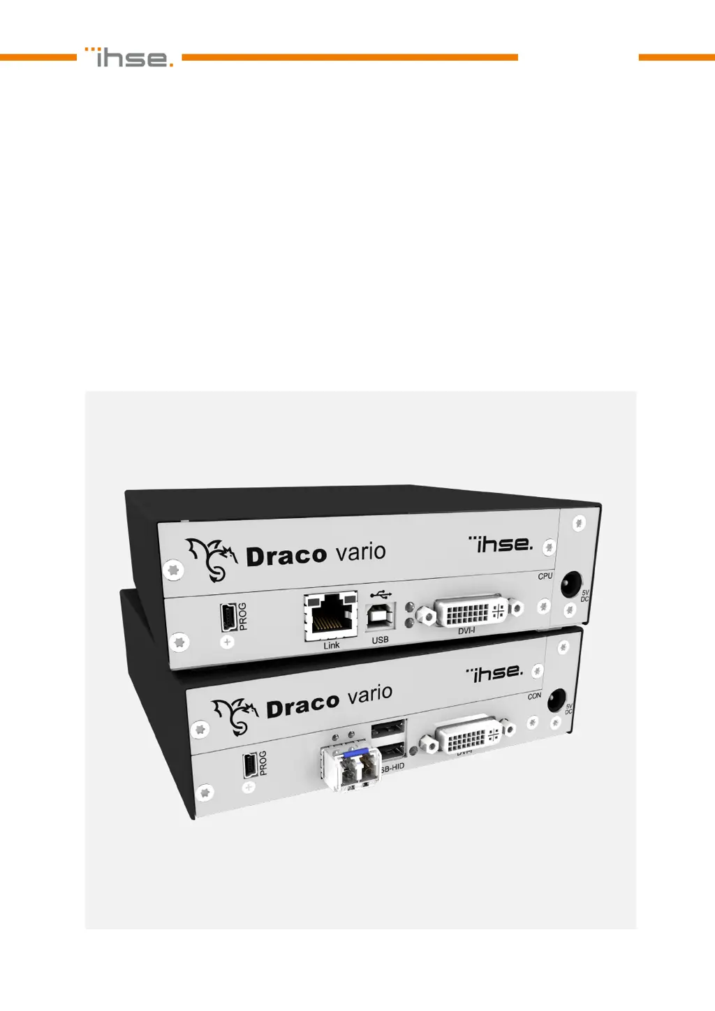
EasyManua.ls Logo

Ihse Draco vario DVI User Manual

Ihse Draco vario DVI
89 pages
To Next Page IconTo Next Page
Page #1 background imageLoading...
Page #1 background image
Document 474_494_REV02.01_en
Edition: 2023-04-03
USER MANUAL
Draco vario DVI
Draco vario ultra DVI
KVM Extender
Series 474
/494

Table of Contents

Questions and Answers:

Ihse Draco vario DVI Specifications

General IconGeneral
BrandIhse
ModelDraco vario DVI
CategoryExtender
LanguageEnglish

Summary

Product Identification

1 Important Information

1.1 Firmware and Software

Manual refers to latest extender firmware available at manual release date.

1.2 Symbols for Warnings and Helpful Information

Explains the meaning of symbols used for warnings and helpful information.

1.3 Terms and Spellings

Defines terms for products, system descriptions, and keyboard commands.

1.4 Intended Use

1.5 Certificates/Directives

1.5.1 North American Regulatory Compliance

Details compliance with FCC rules for Class A digital devices and radio frequency energy.

1.5.2 EU Declaration of Conformity

Provides link to EU Declaration of Conformity and information on obtaining a copy.

1.5.3 WEEE

Explains the WEEE Directive symbol and proper disposal of electrical equipment.

2 Safety instructions

4 Description

4.1 System Overview

Provides an overview of KVM systems and the modular Draco vario system.

4.1.3 System Structure and Terms

Defines KVM pair structure, chassis installation, and module article number recognition.

4.1.4 Embedded Signals

Explains how optional add-on modules transfer embedded audio and USB 2.0 signals.

4.2 System Compatibility

4.2.1 Video Compatibility

Table listing video compatibility between different extender module series.

4.2.2 Interconnection Compatibility

Details compatibility for point-to-point and matrix connections via Cat X and fiber.

4.3 Product Types

4.3.1 DVI-D Extender Modules (Classic Series)

Lists DVI-D Extender Modules (Classic Series) with product type, interconnection, video signal, and USB HID.

4.3.2 DVI-I Extender Modules (Classic Series)

Lists DVI-I Extender Modules (Classic Series) with product type, interconnection, video signal, and USB HID.

4.3.3 DVI-I Extender Modules (Ultra Series)

Lists DVI-I Extender Modules (Ultra Series) with product type, interconnection, video signal, and USB HID.

4.3.4 Supplementary with Extended Function for Extender Modules

Describes SNMP and U-Switch modules for extended functionality.

4.4 Accessories

4.5 Scope of Delivery

4.6 Product Views Extender Modules

4.6.1 Extender Module L-/R474-BSHC/-BVHC

Shows interface side views of L-/R474-BSHC and L-/R474-BVHC CPU and CON modules.

4.6.2 Extender Module L-/R474-BSHCR/-BVHCR

Shows interface side views of L-/R474-BSHCR and L-/R474-BVHCR CPU and CON modules.

4.6.3 Extender Module L-/R474-BSHS/-BSHX/-BVHS/-BVHX

Shows interface side views of L-/R474-BSHS/-BSHX/-BVHS/-BVHX modules.

4.6.4 Extender Module L-/R474-BSHSR/-BVHSR

Shows interface side views of L-/R474-BSHSR and L-/R474-BVHSR CPU and CON modules.

4.6.5 Extender Module L474-BSHCV

Shows interface side view of the L474-BSHCV CPU module.

4.6.6 Extender Module L474-BSHSV/-BSHXV

Shows interface side views of the L474-BSHSV/-BSHXV CPU modules.

4.6.7 Extender Module L494-BVHC

Shows interface side view of the L494-BVHC CPU module.

4.6.8 Extender Module L494-BVHCR

Shows interface side view of the L494-BVHCR CPU module.

4.6.9 Extender Module L494-BVHS/-BVHX

Shows interface side views of the L494-BVHS/-BVHX CPU modules.

4.6.10 Extender Module L494-BVHSR

Shows interface side view of the L494-BVHSR CPU module.

4.7 Status Indication of the Extender Modules

Status LED on Board

Describes the multicolor LED status indication on the PCB of modules in specific chassis.

Link LEDs at the Interface Side

Explains the status of link LEDs for Cat X and fiber extender modules.

4.7.1 Interconnection Cat X

Shows Link LED states for Cat X interconnection and their meaning.

4.7.2 Interconnection Fiber 1G and 3G

Shows Link LED states for Fiber 1G and 3G interconnection and their meaning.

4.7.3 Video and USB HID - Point-to-Point Connection - DVI-D Extender Modules

4.7.4 Video and USB HID - Point-to-Point Connection - DVI-I Extender Modules

LEDs for USB/Video Connection Extender Module L474-BSHxV

4.7.5 Video and USB HID - Matrix Connection - DVI-D Extender Modules

4.7.6 Video and USB HID - Matrix Connection - DVI-I Extender Modules

USB/Video LEDs of Extender Modules L474-BSHxV at the Interface Side

5 Access Options

Command mode

Explains how to access KVM device functions and module settings via keyboard commands.

Management software

Describes firmware updates and additional functions for matrix connections using software.

Mini-USB interface

Explains that extender modules can be parametrized or updated via the Mini-USB interface.

5.1 Command Mode

Hot Key Code

Lists Hot Key codes and explains how to change or reset the Hot Key.

5.2 Management Software

6 Installation

6.1 Setting up the System

Provides step-by-step instructions for installing CON and CPU units and establishing connections.

6.2 Installation Examples

6.2.1 Single Head Installation with Add-on Module Audio

Illustrates a single head installation with an audio add-on module.

6.2.2 Dual Head Installation with Add-on Module USB 2.0

Illustrates a dual head installation with a USB 2.0 add-on module.

6.2.3 Matrix Installation

Illustrates a matrix connection setup for KVM extender modules.

7 Configuration

7.1 Transmission Parameters

Describes transmission parameters for Classic and Ultra Series devices.

7.2 Configuration Options via Mini-USB Service Port

Explains configuration via Mini-USB port, including Config.txt and EDID files.

7.3 EDID Settings

7.4 USB HID Ghosting

7.5 Configuration File

7.6 Parameters

7.6.1 Parameters for CPU Units

Lists parameters for CPU Units related to EDID management, compression, and shared operation.

7.6.2 Parameters for CON Units

7.6.3 Parameters for parallel Operation of redundant CPU Units

8 Operation

8.1 Downloading the EDID

Describes how to load the EDID from a console monitor into the CPU Unit.

8.2 Switching of two different CPU Units via redundant CON Unit

Explains how to switch between two CPU Units using a redundant CON Unit.

9 Summary of Keyboard Commands

9.1 Command Mode

Summarizes keyboard commands to start, exit, and change the Hot Key for command mode.

9.2 Managing of EDID and USB HID Ghosting

9.3 Switching of two different CPU Units via redundant CON Unit

10 Overview of Keyboard Commands

10.1 Keyboard Commands for Configuration

Provides an overview of keyboard commands for configuration tasks.

10.2 Keyboard Commands for Operation

Provides an overview of keyboard commands for operation tasks.

11 Maintenance

11.1 Cleaning of Modules

Provides instructions and warnings for cleaning modules safely.

11.2 Replacing or Mounting additional Modules in Chassis

Refers to the 474-BODY manual for instructions on replacing or mounting modules.

11.3 Updating the Firmware via Management Software

Lists requirements and steps for firmware updates using management software.

11.3 Updating the Firmware via Management Software

11.3.2 Connecting to the Extender Module

Details how to connect the extender module to a computer using a Mini-USB cable.

11.3.3 Updating Firmware via Management Software

Provides steps and notices for performing firmware updates using the management software.

11.3.3 Updating Firmware via Management Software

Management software Flash Update - Search Extender Module

Illustrates the process of searching for extender modules in the management software.

Management software Flash Update - Select Extender Module

Illustrates selecting the extender module and identifying its type during firmware update.

11.3.3 Updating Firmware via Management Software

Management software Flash Update - Identify Extender Module Type

Illustrates the automatic detection and identification of extender module types.

Management software Flash Update - Update Extender Module - Select files

Illustrates selecting firmware files for updating extender modules.

11.3.3 Updating Firmware via Management Software

Management software Flash Update - Update Extender Module - Load files

Illustrates loading firmware files into the management software for updates.

Management software Flash Update - Update Extender Module - Firmware update completed

Shows the completion status of firmware updates and prompts for verification.

11.3.3 Updating Firmware via Management Software

Management software Flash Update - Firmware Check - Firmware verification completed

Illustrates the firmware verification process after an update.

Management software Flash Update - Firmware Check - Complete firmware update

Shows the final step of firmware update completion and prompts to update more modules.

11.4 Updating the Firmware of Extender Modules via Copy & Paste

Preserving the Parameters of the Config.txt File

Instructions to store Config.txt before updating MSD firmware to preserve parameters.

Performing Firmware Updates via Copy & Paste

Detailed steps for manual firmware updates via copy & paste, including parameter preservation.

11.5 Resetting an Extender Module to the Factory Settings

12 Troubleshooting

12.1 General Failures

Lists common failures related to Config.txt parameters and module restarts, with causes and measures.

12.2 Blank Screen with Point-to-Point Connection

Diagnoses and measures for blank screens on DVI-D modules in point-to-point connection.

12.2.2 Blank Screen at DVI-I Extender Modules L-/R474-BVHx and L494-BVHx

Diagnoses and measures for blank screens on DVI-I modules in point-to-point connection.

12.2.3 Blank Screen at DVI-I Extender Module L474-BSHxV

Diagnoses and measures for blank screens on L474-BSHxV module in point-to-point connection.

12.3 Blank Screen with Matrix Connection

12.3.1 Blank Screen at DVI-D Extender Modules L-/R474-BSHx

Diagnoses and measures for blank screens on DVI-D modules in matrix connection.

12.3.2 Blank Screen at DVI-I Extender Modules L-/R474-BVHx and L494-BVHx

Diagnoses and measures for blank screens on DVI-I modules in matrix connection.

12.3.3 Blank Screen at DVI-I Extender Module L474-BSHxV

Diagnoses and measures for blank screens on L474-BSHxV module in matrix connection.

12.4 USB HID Failure with Point-to-Point Connection

12.4.1 USB HID Failure at DVI-D Extender Module L-/R474-BSHx

Diagnoses and measures for USB HID failures on DVI-D modules in point-to-point connection.

12.4.2 USB HID Failure at DVI-I Extender Modules L-/R474-BVHx and L494-BVHx

Diagnoses and measures for USB HID failures on DVI-I modules in point-to-point connection.

12.4.3 USB HID Failure at DVI-I Extender Module L474-BSHxV

Diagnoses and measures for USB HID failures on L474-BSHxV module in point-to-point connection.

12.5 USB HID Failure with Matrix Connection

12.5.1 USB HID Failure at DVI-D Extender Modules L-/R474-BSHx

Diagnoses and measures for USB HID failures on DVI-D modules in matrix connection.

12.5.2 USB HID Failure at DVI-I Extender Modules L-/R474-BVHx and L494-BVHx

Diagnoses and measures for USB HID failures on DVI-I modules in matrix connection.

12.5.3 USB HID Failure at DVI-I Extender Module L474-BSHxV

Diagnoses and measures for USB HID failures on L474-BSHxV module in matrix connection.

13 Technical Data

13.1 Interfaces

Details DVI-D, DVI-I, USB HID, Mini-USB, and RJ45 interfaces.

13.1.6 Fiber SFP Type LC (Interconnect)

Describes fiber communication via Gigabit SFPs with LC connectors.

13.2 Interconnect Cables

Details specifications and recommendations for Cat X cabling.

13.2.2 Fiber

Details transmission problems and specifications for single-mode and multi-mode fiber cables.

Maximum Transmission Range for Video and USB HID Signals (End-to-End Connection)

Specifies transmission ranges for fiber cables with add-on modules and transparent USB.

13.3 Connector Pinouts

Details the pinout for DVI-D and DVI-I Single Link connectors.

13.3.3 USB, Type A

Details the pinout and color coding for USB Type A connectors.

13.3.4 USB, Type B

Details the pinout and color coding for USB Type B connectors.

13.3.5 Mini-USB, Type B

Details the pinout and color coding for Mini-USB Type B connectors.

13.3.6 RJ45 (Interconnect)

Details the pinout for RJ45 interconnect connectors.

13.3.7 Fiber SFP Type LC (Interconnect)

Details the pinout for Fiber SFP Type LC connectors.

13.4 Environmental Conditions and Emissions

13.5 Current Draw and Power Consumption

13.5.1 Current Draw and Power Consumption, Series 474

Table showing current draw and power consumption for Series 474 CPU and CON units.

13.5.2 Current Draw and Power Consumption, Series 494

Table showing current draw and power consumption for Series 494 CPU units.

13.6 Dimensions

13.7 Weight

13.8 MTBF

14 Technical Support

14.1 Support Checklist

Lists information required for efficient technical support requests.

14.2 Shipping Checklist

Provides steps for returning devices, including obtaining an RMA number and packaging.

15 Glossary

18 Change Log

Related product manuals