@ SCREEN YR(Reference Channel Decision)
i) Connect the probe of an oscilloscope to TPl
(RK) on the CRT SOCKET BOARD and
monitor the waveforms from the end of Y.BLK
to start of pictures at a Y rate.
ii) Next, adjust the SCREEN YR until the top of
bias pulse reaches lO0Y DC.
iii) Not changing the range of the oscilloscope,
measure the voltages of bias pulse at TP2(GK)
and TP3(BK) on the CRT SOCKET BOARD.
Then, readjust the channel of the intermediate
voltage among the three channels to lO0Ydc
with the SCREEN YR in order to decide the
reference channel.
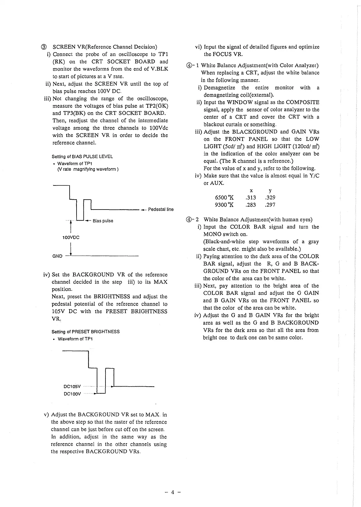
Setting of BIAS PULSE LEVEL
• Waveform of TP1
01 rate magnifying waveform )
.__ ______ --- Pedestal line
t
-- Bias pulse
100VDC
GND ~----------
iv) Set the BACKGROUND YR of the reference
channel decided in the step iii) to its MAX
position.
Next, preset the BRIGHTNESS and adjust the
pedestal potential of the reference channel to
105Y DC with the PRESET BRIGHTNESS
YR.
Setting of PRESET BRIGHTNESS
• Waveform of TP1
DC105V
DC100V
v) Adjust the BACKGROUND YR set to MAX. in
the above step so that the raster of the reference
channel can be just before cut off on the screen.
In addition, adjust in the same way as the
reference channel in the other channels using
the respective BACKGROUND YRs.
- 4 -
vi) Input the signal of detailed figures and optimize
the FOCUS YR.
@- 1 White Balance Adjustment(with Color Analyzer)
When replacing a CRT, adjust the white balance
in the following manner.
i) Demagnetize the entire monitor with a
demagnetizing coil( external).
ii) Input the WINDOW signal as the COMPOSITE
signal, apply the sensor of color analyzer to the
center of a CRT and cover the CRT with a
blackout curtain or something.
iii) Adjust the BLACKGROUND and GAIN YRs
on the FRONT PANEL so that the LOW
LIGHT (Scd/ m') and HIGH LIGHT (120cd/ m')
in the indication of the color analyzer can be
equal. (The R channel is a reference.)
For the value of x and y, refer to the following.
iv) Make sure that the value is almost equal in Y/C
or AUX.
6500°K
9300°K
X y
.313 .329
.283 .297
@- 2 White Balance Adjustment(with human eyes)
i) Input the COLOR BAR signal and tum the
MONO switch on.
(Black-and-white step wavefmms of a gray
scale chart, etc .. might also be available.)
ii) Paying attention to the dark area of the COLOR
BAR signal, adjust the R, G and B BACK-
GROUND YRs on the FRONT PANEL so that
the color of the area can be white.
iii) Next, pay attention to the bright area of the
COLOR BAR signal and adjust the G GAIN
and B GAIN YRs on the FRONT PANEL so
that the color of the area can be white.
iv) Adjust the G and B GAIN YRs for the bright
area as well as the G and B BACKGROUND
YRs for the dark area so that all the area from
bright one to dark one can be same color.
 Loading...