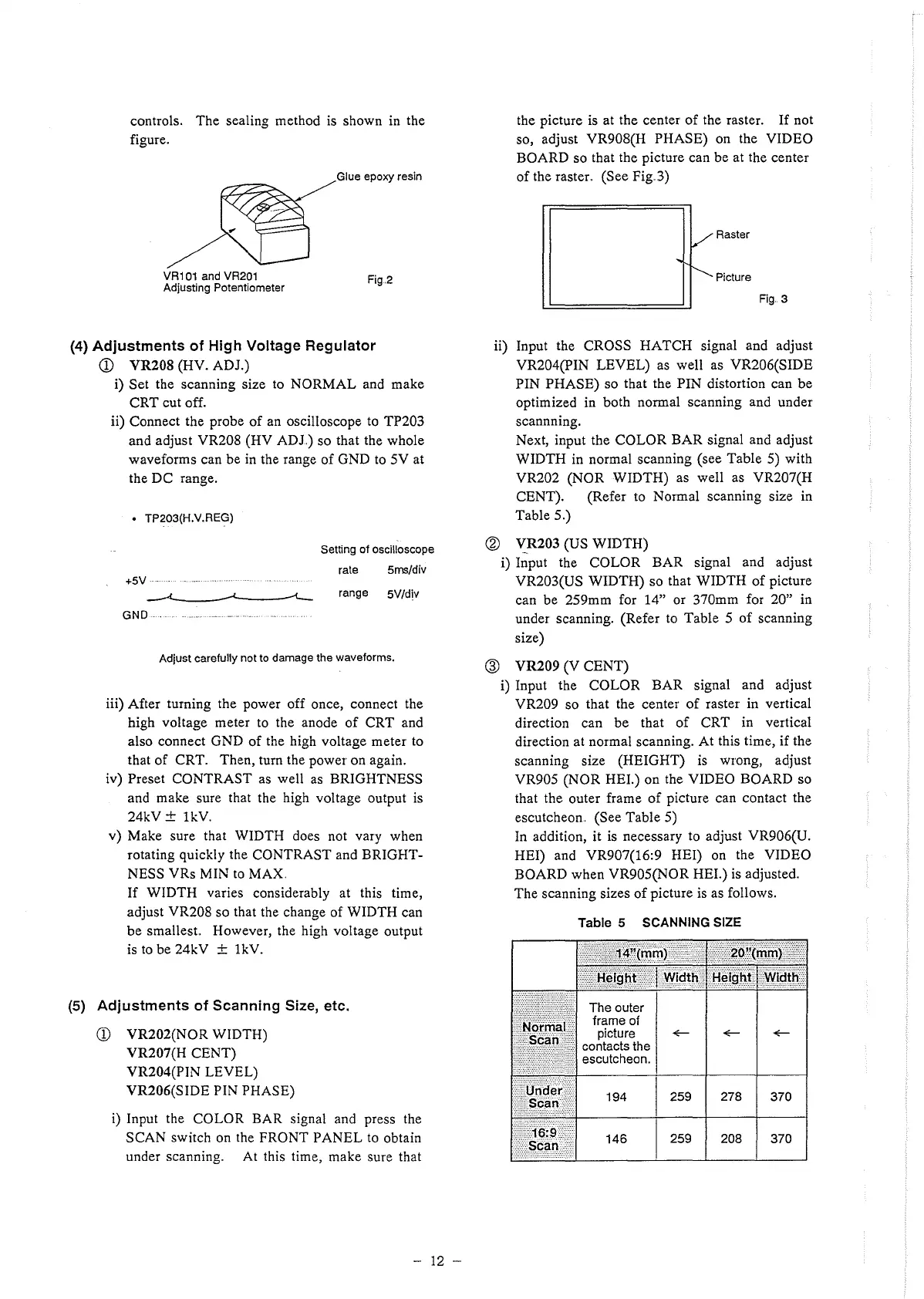
controls. The sealing method is shown in the
figure.
Glue epoxy resin
VR101 and VR201
Adjusting Potentiometer
Fig.2
(4) Adjustments of High Voltage Regulator
CD VR208 (HV. ADJ.)
i) Set the scanning size to NORMAL and make
CRT cut off.
ii) Connect the probe of an oscilloscope to TP203
and adjust VR208 (HV ADJ) so that the whole
waveforms can be in the range of GND to 5V at
the DC range.
• TP203(H.V.REG)
Setting of oscilloscope
rate 5ms/div
+5V
-~ range 5V/div
GND
Adjust carefully not to damage the waveforms.
iii) After turning the power off once, connect the
high voltage meter to the anode of CRT and
also connect GND of the high voltage meter to
that of CRT. Then, turn the power on again.
iv) Preset CONTRAST as well as BRIGHTNESS
and make sure that the high voltage output is
24kV ± lkV.
v) Make sure that WIDTH does not vary when
rotating quickly the CONTRAST and BRIGHT-
NESS VRs MIN to MAX.
If WIDTH varies considerably at this time,
adjust VR208 so that the change of WIDTH can
be smallest. However, the high voltage output
is to be 24kV ± lkV.
(5) Adjustments of Scanning Size, etc.
CD VR202(NOR WIDTH)
VR207(H CENT)
VR204(PIN LEVEL)
VR206(SIDE PIN PHASE)
i) Input the COLOR BAR signal and press the
SCAN switch on the FRONT PANEL to obtain
under scanning. At this time, make sure that
- 12 -
the picture is at the center of the raster. If not
so, adjust VR908(H PHASE) on the VIDEO
BOARD so that the picture can be at the center
of the raster. (See Fig..3)
/
Raster
"
---------
Picture
Fig .. 3
ii) Input the CROSS HATCH signal and adjust
VR204(PIN LEVEL) as well as VR206(SIDE
PIN PHASE) so that the PIN distortion can be
optimized in both normal scanning and under
scannning.
Next, input the COLOR BAR signal and adjust
WIDTH in normal scanning (see Table 5) with
VR202 (NOR WIDTH) as well as VR207(H
CENT). (Refer to Normal scanning size in
Table 5.)
@ V__R.203 (US WIDTH)
i) Input the COLOR BAR signal and adjust
VR203(US WIDTH) so that WIDTH of picture
can be 259mm for 14" or 370mm for 20" in
under scanning. (Refer to Table 5 of scanning
size)
@ VR209 (V CENT)
i) Input the COLOR BAR signal and adjust
VR209 so that the center of raster in vertical
direction can be that of CRT in vertical
direction at normal scanning. At this time, if the
scanning size (HEIGHT) is wrong, adjust
VR905 (NOR HEI.) on the VIDEO BOARD so
that the outer frame of picture can contact the
escutcheon.. (See Table 5)
In addition, it is necessary to adjust VR906(U.
HEI) and VR907(16:9 HEI) on the VIDEO
BOARD when VR905(NOR HEI.) is adjusted.
The scanning sizes of picture is as follows.
Table 5 SCANNING SIZE
 Loading...