@ VR 201 (Y/C Y LEVEL)
Input NTSC COLOR BAR signal to Y/C input
and connect the probe to TPl(RK) on the CRT
SOCKET BOARD. After selecting Y/C, adjust
VR201(Y/C Y LEVEL) so that the white area
of 100% can be 35Vp-p.
(6) Adjustments of VIDEO System- Level Ad-
justment of CHROMINANCE Signal
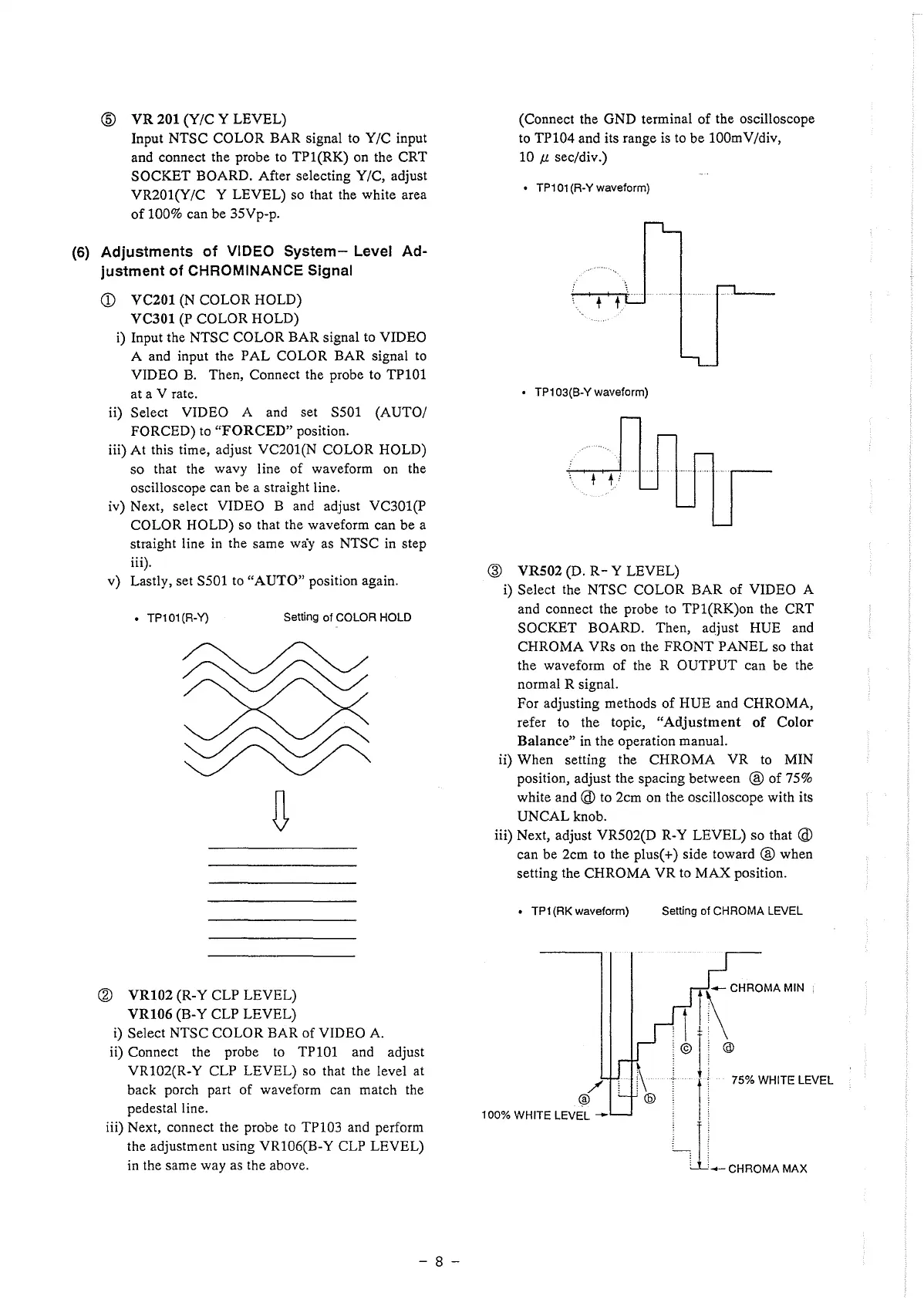
(D VC201 (N COLOR HOLD)
VC301 (P COLOR HOLD)
i) Input the NTSC COLOR BAR signal to VIDEO
A and input the PAL COLOR BAR signal to
VIDEO B. Then, Connect the probe to TP101
at a V rate.
ii) Select VIDEO A and set S501 (AUTO/
FORCED) to "FORCED" position.
iii) At this time, adjust VC201(N COLOR HOLD)
so that the wavy line of waveform on the
oscilloscope can be a straight line.
iv) Next, select VIDEO B and adjust VC301(P
COLOR HOLD) so that the waveform can be a
straight line in the same way as NTSC in step
iii).
v) Lastly, set SS0l to "AUTO" position again.
• TP101 (R-Y)
Setting of COLOR HOLD
@ VR102 (R-Y CLP LEVEL)
VR106 (B-Y CLP LEVEL)
i) Select NTSC COLOR BAR of VIDEO A.
ii) Connect the probe to TPlOl and adjust
VR102(R-Y CLP LEVEL) so that the level at
back porch part of waveform can match the
pedestal line.
iii) Next, connect the probe to TP103 and perform
the adjustment using VR106(B-Y CLP LEVEL)
in the same way as the above.
- 8 -
(Connect the GND terminal of the oscilloscope
to TP104 and its range is to be lO0mV/div,
10 µ sec/div.)
• TP101 (R-Y waveform}
• TP103(B-Y waveform}
@ VR502 (D. R- Y LEVEL)
i) Select the NTSC COLOR BAR of VIDEO A
and connect the probe to TPl(RK)on the CRT
SOCKET BOARD. Then, adjust HUE and
CHROMA VRs on the FRONT PANEL so that
the waveform of the R OUTPUT can be the
normal R signal.
For adjusting methods of HUE and CHROMA,
refer to the topic, "Adjustment of Color
Balance" in the operation manual.
ii) When setting the CHROMA VR to MIN
position, adjust the spacing between @ of 75%
white and @ to 2cm on the oscilloscope with its
UNCALknob.
iii) Next, adjust VR502(D R-Y LEVEL) so that @
can be 2cm to the plus(+) side toward @ when
setting the CHROMA VR to MAX position.
• TP1 (RK waveform) Setting of CHROMA LEVEL
100% WHITE LEVEL --
.
1
ff~ CHROMA MIN
© l @
. r 1 75% WHITE LEVEL
j J,_ CHROMA MAX
 Loading...