@ Tum "OFF" all ISCREENI switches to set to
all-white screen.
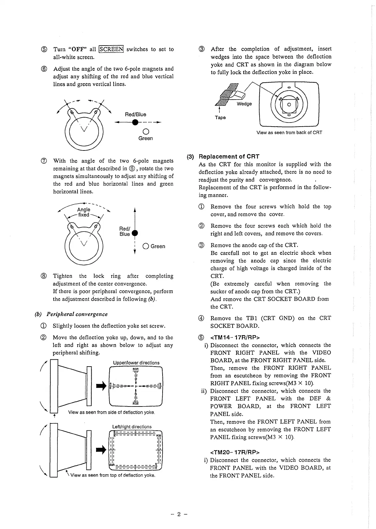
@ Adjust the angle of the two 6-pole magnets and
adjust any shifting of the red and blue vertical
lines and green vertical lines.
Red/Blue
.. . ----
0
Green
(J) With the angle of the two 6-pole magnets
remaining at that described in @, rotate the two
magnets simultaneously to adjust any shifting of
the red and blue horizontal lines and green
horizontal lines.
A)
Blue'
I
1 Q Green
t
@ Tighten the lock ring after completing
adjustment of the center convergence.
If there is poor JJeripheral convergence, perform
the adjustment described in following (b)..
(b) Peripheral convergence
CD Slightly loosen the deflection yoke set screw.
® Move the deflection yoke up, down, and to the
left and right as shown below to adjust any
peripheral shifting.
(
\
t
(
\
Upper/lower directions
BOR
T
➔
~
..... 1-~--ea--=---
e F - - - • 1
ROB
View as seen from side of deflection yoke.
LefVright directions
-----R33
11
11
➔
II
11
11
11
11
11
11
11
11
11
- - - - -§' .
\ View as seen from top of deflection yoke.
@ After the completion of adjustment, insert
wedges into the space between the deflection
yoke and CRT as shown in the diagram below
to fully lock the deflection yoke in place.
A,.
t
Tape
View as seen from back of CRT
(3) Replacement of CRT
As the CRT for this monitor is supplied with the
deflection yoke already attached, there is no need to
readjust the purity and convergence.
Replacement of the CRT is performed in the follow-
ing manner.
CD Remove the four screws which hold the top
cover, and remove the cover.
® Remove the four screws each which hold the
right and left covers, and remove the covers.
@ Remove the anode cap of the CRT.
Be carefull not to get an electric shock when
removing the anode cap since the electric
charge of high voltage is charged inside of the
CRT.
(Be extremely careful when removing the
sucker of anode cap from the CRT.)
And remove the CRT SOCKET BOARD from
the CRT.
@ Remove the TBl (CRT GND) on the CRT
SOCKET BOARD.
@ <TM14·- 17R/RP>
i) Disconnect the connector, which connects the
FRONT RIGHT PANEL with the VIDEO
BOARD, at the FRONT RIGHT PANEL side.
Then, remove the FRONT RIGHT PANEL
from an escutcheon by removing the FRONT
RIGHT PANEL fixing screws(M3 X 10)..
ii) Disconnect the connector, which connects the
FRONT LEFT PANEL with the DEF &
POWER BOARD, at the FRONT LEFT
PANEL side.
Then, remove the FRONT LEFT PANEL from
an escutcheon by removing the FRONT LEFT
PANEL fixing screws(M3 X 10}
<TM20- 17R/RP>
i) Disconnect the connector, which connects the
FRONT PANEL with the VIDEO BOARD, at
the FRONT PANEL side.
- 2 -
 Loading...