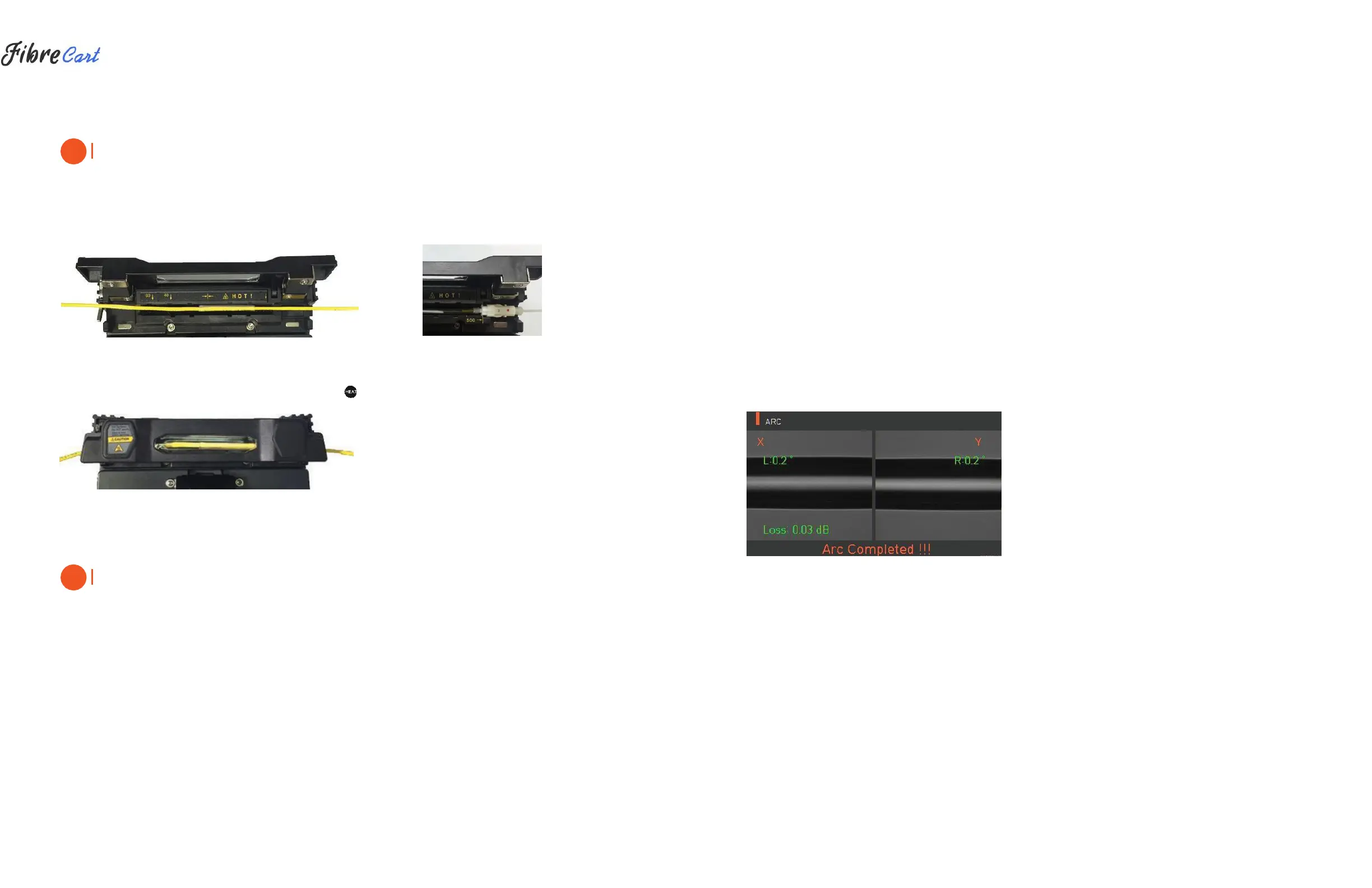
CAUTION
Choosing the improper mode of the heater for a sleeve tube may not shrink the sleeve tube properly. Specifically,
the SOC (Splice-On-Connector) should be placed on the right side edge of the heater in order to line up the
right end of the sleeve tube to the right side edge of the heater as shown on the picture below (Right picture). If
the SOC is placed in the middle or on the left side, the sleeve tube of the SOC does NOT shrink.
|
OPTICAL FIBER
|
SOC CONNECTOR
3| After settling the fiber, turn on the heater by pressing . (Heating time 20sec)
4| Remove the sleeve protected fiber by opening the cover when the cooling is completed.
CAUTION
The appropriate sleeve position helps reduce heating operation time.
4.4
| SPLICE PROCEDURE
The status and cleaved quality of the fiber can be monitored by using a KF4 image processing system.
However, for better splice results, visual inspection is also required.
In auto mode, the splicing procedure begins automatically as the wind cover is closed.
1| Fibers installed on the splicer advance toward each other and stop. The fibers align once arc cleaning is
done. After that, the splicer checks the cleaved angle of each fiber, the shape of the end-face contaminations
and so on. When the measured cleaved angle is bigger than the preset value, or damage is detected on the
fiber, an error message is displayed on the screen. The splice procedure stops as well. Even if there is no error
message displayed, visual inspection of the monitor screen is always recommended.
2| Check that the Wind cover is properly closed at more than 900µm cable (Ø2.0~Ø3.0µm)
3| Fibers are aligned, cladding to cladding, after inspection. Deviation on clad axis can be displayed on
the screen.
4| After alignment completes, arcing is conducted to splice fibers.
5| After splicing is completed, the estimated value of the loss is displayed on the screen. The estimated value of
splice loss is subject to various factors related to the error. These factors related to an error affect the estimation
and calculation of estimated loss value as well. Calculation of estimated loss is based on factors such as MFD.
When estimated loss value exceeds the preset value, an error message is displayed on the screen. The error
message is also displayed when the spliced fibers are too thick or thin, or when bubbles are generated on the
spliced point. If the splice result shown on the screen is not considered good enough, it is recommended that
splicing be conducted again.
6| The splice result is saved as follows.
7| When splice is completed, the splice result is automatically saved.
4.5
| REMOVING THE SPLICED FIBER
1| Open the cover of the sleeve heater.
2| Open the wind cover.
3| Hold the fiber on the left and open the clamp on the left.
4| Open the fiber clamp on the right.
5| Hold both sides of the spliced fiber and separate the fiber from the KF4 with care.
4.6
| HEATING PROTECTION SLEEVE
1| Move the spliced point to the center of the protecting sleeve. Place the protected pin face down in the sleeve.
2| Place the protecting sleeve at the center of the sleeve heater.
 Loading...