INSTALLATION
Wiring diagrams
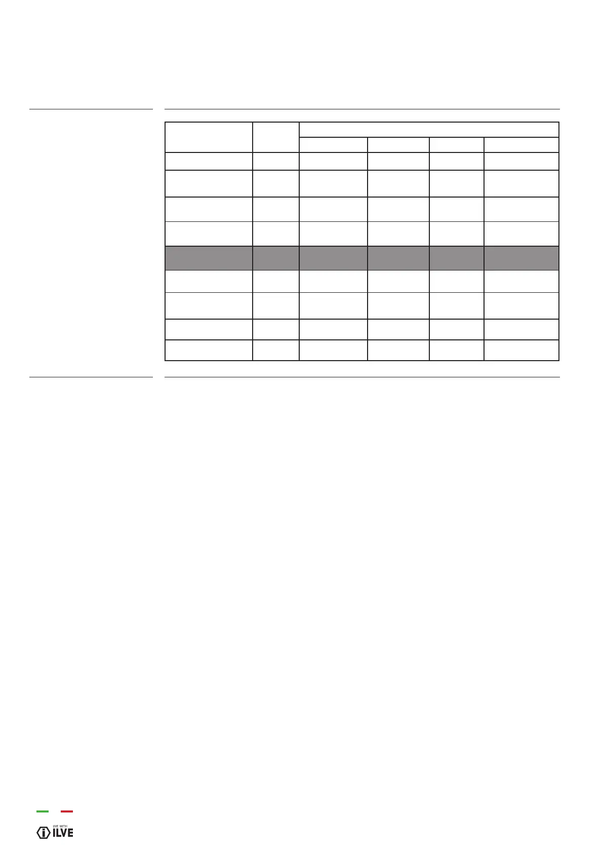
Absorption (kW)
Key
00 Black
11 Brown
22 Red
33 White
44 Yellow
45 Yellow-Green
55 Grey
66 Blue
C Commutator
CP Cooking probe
DU Thermal actuator
discharging steam
EF Functions encoder
ET Thermostat encoder
F Phase
FLC Filter
K1 Earth wire terminal block
K2 “ “ Lower resistance
K3 “ “ oven fan
K4 “ “ circulating resistance
K5 “ “ upper resistance
K6 “ “ oven light 1
K7 “ “ oven light 2
K8 “ “ roaster
K9 “ “ cooling fan
K11 “ “ oven thermostat
K12 “ “ programmer/timer
K15 “ “ frame
L1 Oven light
L2 Oven light
M Terminal block
MG Roaster
MP Door micro switch
N Neutral
NTC Temperature probe
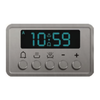
P Timer/Programmer
P Timer/Clock
R1 Upper resistance
R2 Lower resistance
R3 Grill resistance
R4 Circulating resistance
S1 Oven warning light
S2 Mains warning light
SD Display board
SE Selector
SP Power board
SS Probe board
T Grill thermostat
TF Oven thermostat
TS Safety thermostat
TT Bypass thermostat
TST Safety cooling fan thermostat
V Oven fan
VT Cooler fan
SA Supply
GL LED light
NTC Probe NTC
PT1000 “ PT1000
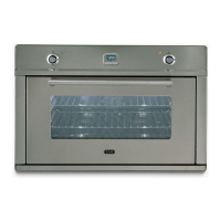
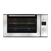
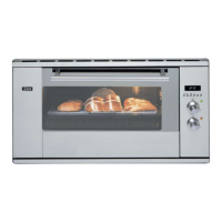
Model
kW
(230V)
Resistance
Bottom (kW) Top (kW) Grill (kW) Fan (kW)
OV60 2,45 1,1 1 2,1 2,1
OV80 - OV948
OV90
2,7
5
1,35 1,2 2,15 2,1
OV30
3,1
1,6 1,2 3,0 2x1,05
OV91
2,95
1,6 1,2 2,15 2,1
with Quickstart -- -- -- --
OV60 3,2 1,1 1 2-1
2,1
OV80 - OV948
OV90
3,40 1,35 1,2
2,15 2,1
OV30 3,40 1,6 1,2 3,0 2x1,05
OV91 3,4 1,6 1,2 2,15 2,1
36
 Loading...