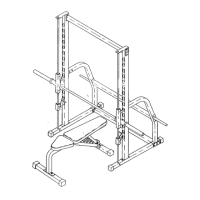
18
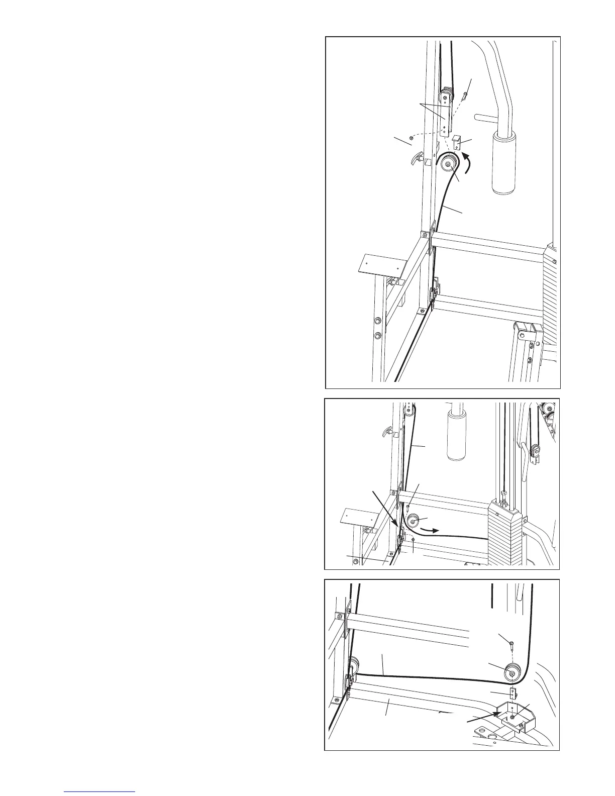
39. Wrap the Low Cable (75) around a 3 1/2” Pulley (24)
in the direction shown. Attach the Pulley and a Cable
Trap (25) to the second hole from the bottom of the
A
djustable Pulley Plates (23) with a 3/8” x 2” Bolt (54)
and a 3/8” Nylon Locknut (50). Make sure the Cable
T
rap is oriented as shown.
39
54
25
75
23
24
5
0
40. Wrap the Low Cable (75) around a 3 1/2” Pulley (24)
in the direction shown. Attach the Pulley to the weld-
ed bracket on the Butterfly Base (4) with a 3/8” x
1 3/4” Bolt (57) and a 3/8” Nylon Locknut (50).
40
50
4
24
75
57
41. Note: For clarity, the weight stack is not shown.
Wrap the Low Cable (75) around a 3 1/2” Pulley (24)
in the direction shown. Attach the Pulley and a Cable
Trap (25) to the welded bracket on the Weight Base
(5) with a 3/8” x 2” Bolt (54) and a 3/8” Nylon Locknut
(50). Make sure the Cable Trap is oriented as
shown.
41
24
75
5
25
50
54
Welded
Bracket
Welded
Bracket