Chapter 2
Installation
8
Copyright © 2011, Harris Corporation
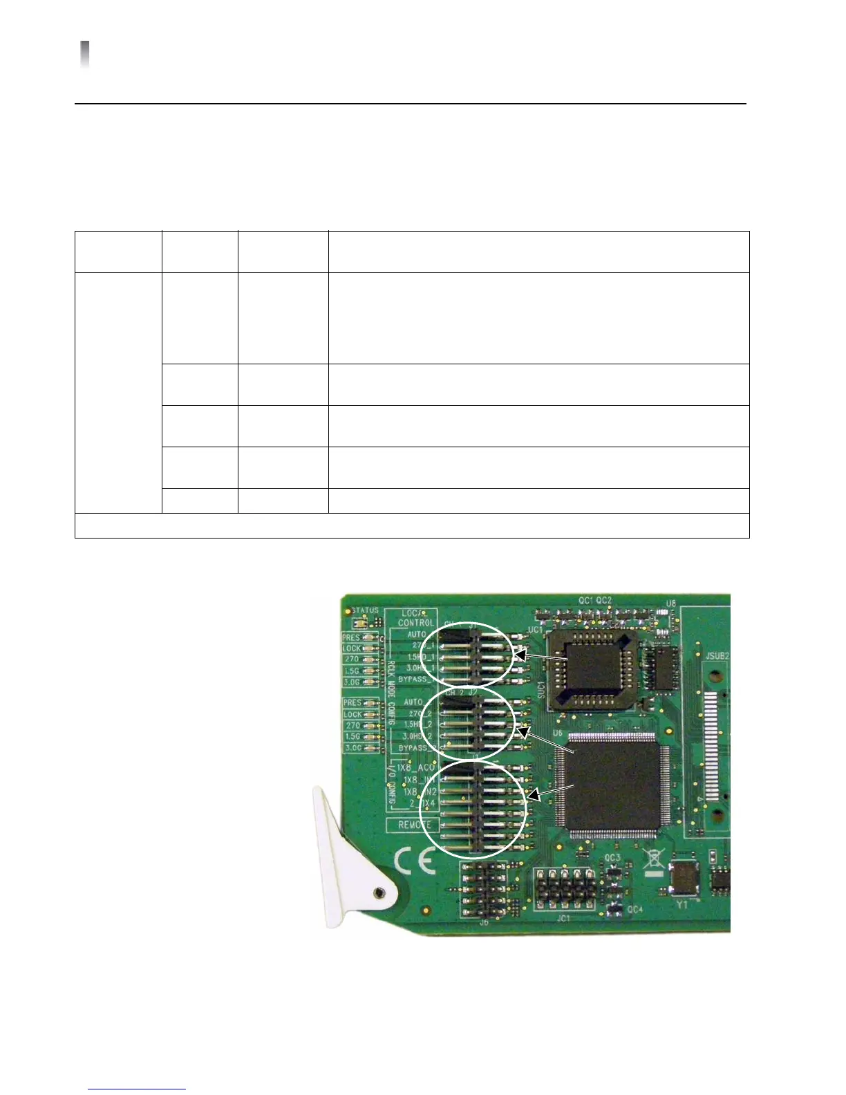
Jumpers J1 and J2 (DA-DSR6804+D and DA-DHR6804+D)
To set the reclocker mode for the DA-DSR6804+D and DA-DHR6804+D at the
card-edge, use Jumper J1 (for channel 1) and Jumper J2 (
for channel 2). The
reclocker remains in AUTO mode if no jumper is set.
Figure 2-1 Lo
cations for Jumpers J1, J2, and J3
Table 2-1 J1
and J2 Jumper Settings
Jumper
Selection
Pin
Setting
Label Description
J1/J2
(Channel 1/
Ch
annel 2)
1/2 AUTO_1/2 Input signal locked at one of these data rates:
2.97 Gb/s*
1.485 Gb/s*
270 Mb/s
If not lockable, signal automatically bypasses reclocker
3/4 3.0G_1/2 Input signal locked at 2.97 Gb/s*; if not locka
ble, signal automatically
bypasses reclocker
5/6 HD_1/2 Input signal locked at 1.485 Gb/s*; if not lockable, signal
automatically bypa
sses reclocker
7/8 SD_1/2 Input locked at 270 Mb/s; if not lockable, signal a
utomatically
bypasses reclocker
9/10 BYPASS_1/2 Enforces signal bypass reclocker
*Not applicable to the DA-DSR6804+
Jumper
J1
Jumper
J2
Jumper
J3