1903KITINT18_230 – 1903KITINT18_400 (E121001A_ENG) 26/10/2012
6
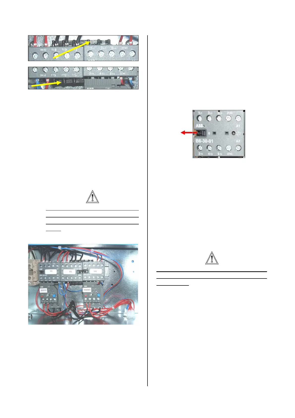
e) Install the motor thermal on the
terminals T1-T2-T3 of the
contactor DX. The previously
installed equipotential bar must be
clamped.
f) Install the wiring code T110609X
(supplied), which replace comletely
the previous wiring limited to the
contactor VE. The wiring is
provided with a 9 poles white
connector which can receive and
send signal to the control board on
the machine front.
The CABLE-TERMINAL
correspondence is highlighted in
the electrical diagram of the last
page.
g) Insert the three terminals of the
T110301X motor wiring (supplied)
into the three free places of the 6
poles white connector. The 6 poles
connectors is on the bottom of the
electric box. The cable position
coming from the motor can be
casual.
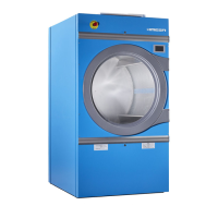
7. WORKING TEST
Each single contactor can be tested.
Using a screwdriver, push the pin until the
contact is completely closed. In this
situation, check the correct sense of
rotation and, if necessary, invert the two
phase in output.
.
8. THERMAL MOTOR ADJUSTMENT
To protect the fan and drum motor, the
two thermal relays must be set to a
threshold equal to the motor nominal
current.
To adjust the thermal devices, use the
small wheel of each device.
Using an ammeter control the current
absorbed from each motor, then set the
thermal to the value measured.
Do not set the thermal relay to the
maximum of its capacity: motors
could burn.
For a correct working, be sure that all the
three phases are correctly connected to
the drum motor with the nominal tension
of the electric system.