Electrical connection M 12 x 1 *
Pin
Signal
Cable
1
+ U
B
brown
2
Out 2 (PNP) / analog 4 to 20 mA
white
3
0 Volt
blue
4
Out 1 (PNP)
black
5
PE
grey
2.2 Hysteresis-MODE:
During the course of the set point setting either the switch-on flank (n.o status) or the switch-off flank (n.c status) will
blink, depending on the operating mode. When setting the hysteresis mode consequently the hysteresis mode will
blink. Depending on the set polarity (n.c. / n.o. see setup) the hysteresis diagram will appear on the display with the
adjustable switching flank blinking.
Picture 2: Switching OUT 1n.o., switching OUT 2 n.c.
2.3 Window MODE:
This operating mode provides the definition of a switching point and a reset point within a pressure range. In case the
prevailing pressure is within this "window”, the switching out will be activated (polarity n.o.) or inactivated (polarity
n.c.)
Picture 3: Switching OUT 1 n.o., switching OUT n.c.
3.
Error- and warning messages:
LO VOLT
Supply voltage too low
LO TEMP
Temp. Signal too low or sensor defect
HI PRES
Pressure signal too high or sensor defekt
CALI
Pressure switch not properly calibrated
LO PRES
Sensor defect
ESET
Pressure switch not properly
calibrated
HI TEMP
Temp. Signal too high or sensor defect
ESH1 (2)
SETUP settings OUT 1 (2)
for mode, on/off time not correct
4.
Despatch settings Your settings
– Display bar
– Switching mode Standard n. o.
– Switch on/off delay 0 sec.
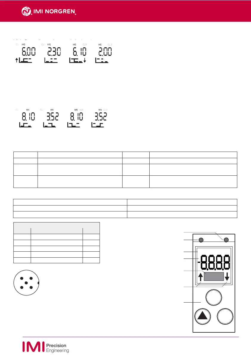
Function keys and display
LED Output 2 (optional)
LED Output 1
Indication for Operating MODE
7-segment display (4 digits)
OUT1 HYS WIN
OUT2
3 2
5
*
Must only be connected to PELV
4
1
circuits VDE 0100 part 410.
Dot-Matrix for additional informations
Indication during adjusting setpoint and
resetpoint
Keypad with 3 buttons
SET
▼
9
7503442.99.10.01
EN
Subject to change without notice