3-7
34
INSTALLERUSER
MAINTENANCE TECHNICIAN
3.9 UNIT PROTECTION DEVICES.
* Protection logic of the 6 starts/h has priority.
Attention: during operation in heat pump heat-
ing mode, the unit executes defrosting cycles to
remove any ice that formed on the outdoor unit
due to low temperatures.
3.10 ANNUAL MAINTENANCE.
Cleaning the battery.
If required, for more accurate cleaning of the
battery, follow the instructions below:
- Switch the supply voltage circuit o.
- Remove the upper cover of the unit by loos-
ening the fastening screws.
- Li the cover.
- Clean the battery thoroughly with a vacuum
cleaner, starting from inside and moving
outwards.
- Using the said vacuum cleaner, remove any
dust from the chamber and fan blades.
- Take care not to damage the blades in order
to prevent vibrations or unusual noises.
- Replace the cover and tighten the fastening
screws.
- Check the seal of the assembly elements
(screws, bolts, plugs, structural elements, etc.)
- Check that the system is in good condition.
- Visually check for water leaks or oxidation
from/on connections.
- Visually check that the safety and control
devices have not been tampered with.
Safety Check Engagement Release
Hydraulic circuit pressure switch 300kPa N.A.
Antifreeze Protection Adjustable from 3 to 9°C controlled by the soware
Compressor Start Delay OFF-->ON 180 s max*
Compressor Stop Delay ON-->OFF 180 s*
Compressor starting limit 6 starts/h*
Vent
Any air present in the system must be bled:
- upon start-up (aer lling)
- if necessary, e.g. in the event of breakdown.
Attention: the operation must be carried out by
qualied personnel.
Check the coolant load.
is check is required when a coolant leakage has
occurred or the compressor has been replaced.
e best system used to execute proper coolant
loading is to empty the cooling circuit completely
through the special coolant recovery device,
then insert the exact same amount of coolant
according to what is indicated on the unit's
identication plate features.
R-410A systems must be loaded with liquid phase
coolant. Use the special reloading device (found
on the market) to ensure proper coolant manage-
ment. e oil used in the compressor is ESTER
OIL VG74 (VG68 for Audax TOP 12 ErP).
Attention: do not use coolants or lubricants that
dier from those specied. Do not compress
air (Avoid air caused by leakages in the cooling
circuit)
Should you be required to reload coolant, load
the specic amount according to the following
steps:
1) Recover the coolant and make sure there are
no traces in the device.
2) Connect the load pipe to the valve service
opening.
3) Connect the load pipe to the vacuum pump
adapter.
4) Position the lower handle of the manifold pres-
sure gauge in a completely open position and
start the vacuum pump. Evacuate the coolant.
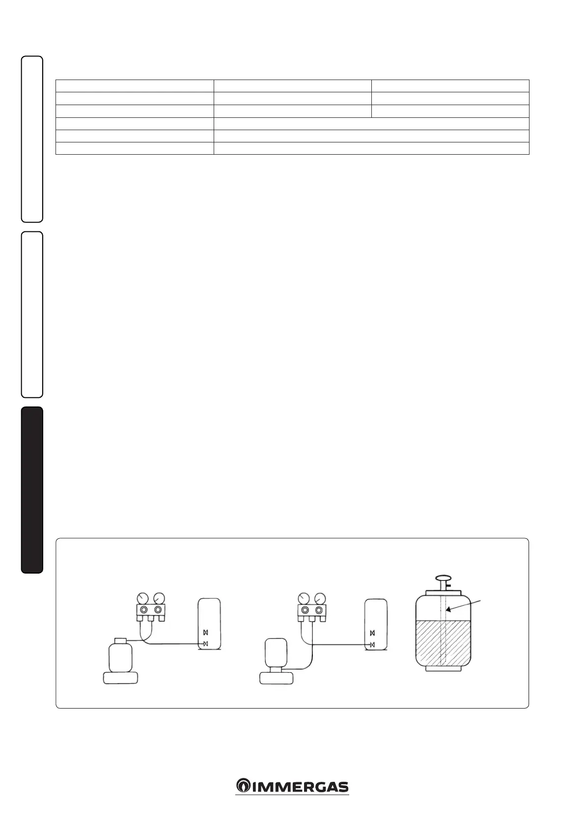
Dip pipe
External unitExternal unit
Pressure gauge
unit
Manifold
pressure gauge
Cylinder with siphon Cylinder without siphon
Electronic scaleElectronic scale
Coolant
cylinder
Coolant
cylinder
5) When the pressure gauge indicator indicates
-0.1 MPa (-76 cmHg), position the lower han-
dle in a completely closed position and switch
o the vacuum pump.
6) Keep the set condition for 1 or 2 minutes and
make sure that the pressure gauge indicator
does not go higher.
7) Connect the coolant cylinder to the manifold
and open connection to load the coolant and
reach the requested amount.
Important:
- Never load an excessive amount of coolant.
- If the amount of coolant requested cannot be
loaded, load the coolant bit by bit in COOL
mode.
- Do not load additional coolant. When addi-
tional loading is executed, the coolant will
overow and its composition changes the
cooling cycle, which means the heat pump
features change since more coolant than
requested is loaded and the cooling cycle
pressure becomes too high causing possible
damage or injury to people.
- A cylinder with a siphon enables the liquid to
be loaded without turning the cylinder upside
down (refer to gure 3-7)

 Loading...