8
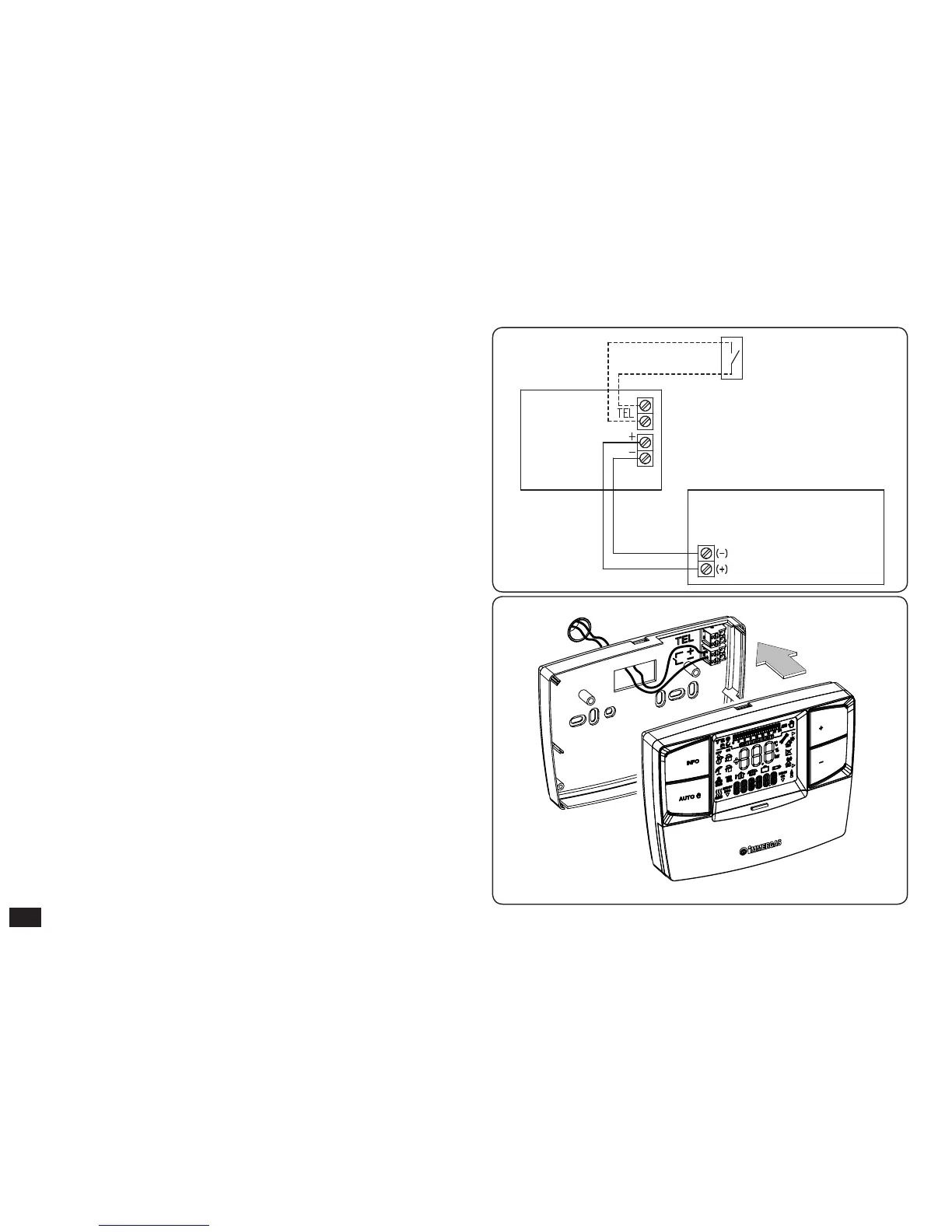
Fig. 5
Fig. 4
3) To make the electrical connections (Fig. 4) do not operate
when the boiler is live. e connection must be made
respecting the polarity of the wires (+ and -). e jumper
on clamps 40 and 41 of the boiler P.C.B. (if present) must
also be eliminated.
Connect the CAR
V2
remote control to the boiler clamps
envisioned at communication with the CAR remote control
or, if not present, to the clamps envisioned for the CRD.
Note: refer to the electrical connections stated in the boiler
instruction book.
e connection to the boiler is made using two wires (Fig.
5)with minimum section of 0.50 mm
2
and maximum of 1.5
mm
2
and with maximum length of 50 metres.
N.B: for correct installation prepare a dedicated line for the
connection of the CAR
V2
remote control according to the
Standards in force regarding electrical systems. If this is not
possible interference due to other electric cables could cause
malfunctioning of the CAR
V2
remote control itself.
4) Fix the body of the CAR
V2
remote control to the support
template, engaging it with pressure and using the two screws
provided (Fig. 3).
5) Aer the boiler has been powered, wait about 30 seconds
before regulation in a way that the communication between
CAR
V2
remote control and boiler has established.