EasyManua.ls Logo

Immergas EOLO 27 Maior User Manual

Immergas EOLO 27 Maior
30 pages
To Next Page IconTo Next Page
Page #1 background imageLoading...
Page #1 background image
Technical documentation Technical documentation
STEM@ ed 06/01
1
EOLO MAIOR @
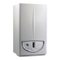
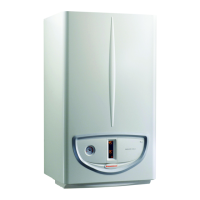
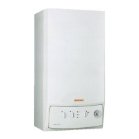
EOLO Maior @
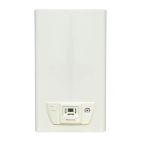
Instantaneous wall-hung boilers
with sealed combustion chamber
fan assisted
EOLO 21 Maior @
EOLO 24 Maior @
EOLO 27 Maior @
- GENERAL FEATURES
The EOLO Maior @ series comprises sealed-chamber boilers with forced draught (fan assisted) for
central heating and the production of domestic hot water.
The range includes electronic-ignition versions with working outputs of 21,000 kcal/h (24.4 kW), 24,000
kcal/h (27.9 kW) and 27,000 kcal/h (31.4 kW).
Adjustment and control of the boiler are entrusted to a microprocessor-controlled electronic board
thanks to which the appliance can be connected to the Remote Friend Control (optional).
The hydraulic circuit features a copper water-gas exchanger, an automatic system by-pass and a new
brass monobloc to which is fitted the hydraulic 3-way valve which ensures, according to need,
circulation of boiler water in the heating system or in a stainless-steel plated exchanger for the
instantaneous production of d.h.w.
Combustion air flow into the sealed chamber and flue extraction are ensured by a fan, the correct
operation of which is controlled by a differential pressure switch.
All the models feature as standard an antifreeze safety device that protects down to temperatures
as low as -5°C.
- MAIN DIMENSIONS AND CONNECTIONS
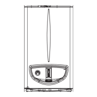
DIMENSIONS (mm)
HEIGHT WIDTH
DEPTH
EOLO 21/24/27
850 450 350
CONNECTIONS
GAS
D.H.W.
SYSTEM
G U E R M
EOLO 21/24/27
1/2 “ 1/2 “ 1/2 “ 3/4 “ 3/4 “
V - power connection
G - gas supply
U – domestic hot water outlet
E – domestic hot water inlet
R - system return
M - system flow
Question and Answer IconNeed help?

Do you have a question about the Immergas EOLO 27 Maior and is the answer not in the manual?

Immergas EOLO 27 Maior Specifications

General IconGeneral
BrandImmergas
ModelEOLO 27 Maior
CategoryBoiler
LanguageEnglish

Summary

Hydraulic Circuit Details

Hydraulic Circuit for EOLO Maior 21-24-27

Diagram and explanation of the hydraulic circuit for EOLO Maior 21-24-27 @ models.

Hydraulic Circuit for EOLO Maior 21-24 S

Diagram and explanation of the hydraulic circuit for EOLO Maior 21-24 S @ models.

Primary Circuit Operation

Details the primary circuit operation, heat absorption, and water flow.

Safety Devices and Controls

Hydraulic Circuit - Secondary (DHW)

Secondary Circuit for DHW

Details the secondary circuit for domestic hot water production.

DHW Operation

Explains how the secondary circuit operates when domestic hot water is requested.

Domestic Hot Water Exchanger

Describes the stainless-steel plate exchanger for D.H.W. heat exchange.

Hydraulic 3-Way Valve Operation

Hydraulic 3-Way Valve Components

Explains the function and components of the hydraulic 3-way valve.

3-Way Valve Operating Position for DHW

3-Way Valve Operating Position (Domestic Hot Water)

Details the valve's operation during domestic hot water demand.

Gas Circuit Components and Operation

Gas Circuit Operation

Explains the gas flow and mixing process for combustion.

Modulating Gas Valve

Describes the modulating gas valve and its control components.

Burner Components

Details the burner construction, nozzles, and ignition system.

Gas Pressure Adjustments

Gas Valve VK 4105 M Adjustments

Instructions for minimum and maximum pressure adjustments on the VK 4105 M valve.

Gas Valve VK 4105 M-M Adjustments

Procedures for adjusting gas pressure on the M-M version of the valve.

Changing Gas Type

Procedure for Changing Gas Type

Guide to adapting the boiler for different gas types (natural gas or LPG).

Flue Circuit Description

Flue Circuit Operation

Explains the combustion residue path and fan operation for flue extraction.

Flue Pressure Switch and Fan

Extraction and Exhaust Systems

Electrical Circuit - 230V AC

230V AC Circuit Safety Devices and Controls

Details safety devices operating at mains voltage and their functions.

Electrical Circuit - Low Voltage

Low-Voltage Circuit Safety Devices and Controls

Lists low-voltage safety devices and controls and their functions.

Electrical Circuit - Central Heating Phase

Electrical Circuit - DHW Phase

Modulation Card Functions

Modulation Card Description

Describes the microprocessor-controlled electronic board and its functions.

Modulation Card Central Heating Operation

Explains how a room thermostat request initiates central heating and burner operation.

Outputs and Adjustments

Temperature Adjustments

Sets central-heating and domestic hot water temperatures using potentiometers.

Safety Devices and Indicators

Boiler Operating Sequences

Heating Phase Operating Sequence

Details the step-by-step sequence for central heating operation.

DHW Phase Operating Sequence

Outlines the sequence of operations for domestic hot water production.
EOLO Maior Technical Data

Combustion Parameters and EOLO 21 Adjustments

Heat Output Adjustments for EOLO 24 and 27

Related product manuals